Instructions for optional systems, Button station, Qcc is designed for slide gate operators only – Controlled Products Systems Group HCT5011O3-08 User Manual
Page 17: Warning, Relay contact rating, Omni option board see accessories page, Made in usa, N.o. com n.c
15
CENTER
SAFETY
EXIT
CENTER
SAFETY
EXIT
FIRE
DEPT.
1
3
STRIKE
OPEN
RADIO
RECEIVER
TIMER
SYSTEM ON
EXIT
LOOP
ALARM
SENSOR
REVERSE
SENSOR
OPEN
STOP
CLOSE
SAFETY
LOOP
CENTER
LOOP
GATE
LOCKED
60
POWER
OVERLOAD
OFF
W4
OPEN LEFT
DC-BACKUP
ALARM
SENSOR
OPEN RIGHT
3
SENSORS
RESET
MOTOR
1
3
1
3
COMMAND
PROCESSED
ON
G B
MS LINK
A
MADE IN USA
QCC
A
B
OPEN
STOP
CLOSE
MAGLOCK
ALARM
ARMED
M / S L I N K
QCC
A
B
OPEN
STOP
CLOSE
MAGLOCK
ALARM
ARMED
M / S L I N K
2 3 4 5 6 7 8 9 10 11
12
13 14
15
1
3 5
1
16
Omni Option Board
see Accessories page
– Open Command
– Stop Command
– Close Command
– Common
– Normally Closed
– Normally Open
Master/Second
RS485
– Burglar Alarm Output
– Burglar Alarm Input
– Ground
– B
– A
10
&
11
12
&
13
14
15
16
Gnd
Gnd
Gnd
Gnd
Gnd
B
A
N.O.
N.O.
N.O.
N.O.
N.C.
N.C.
N.C.
Com
Com
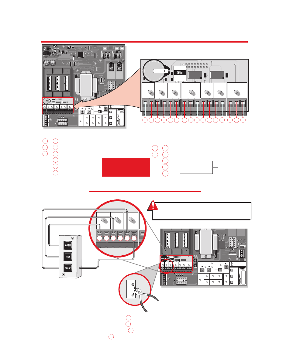
QCC is designed for slide gate operators only!
3 - B U T T O N S T A T I O N
I N S T R U C T I O N S F O R O P T I O N A L S Y S T E M S
CENTER
SAFETY
EXIT
CENTER
SAFETY
EXIT
FIRE
DEPT.
1
3
STRIKE
OPEN
RADIO
RECEIVER
TIMER
SYSTEM ON
EXIT
LOOP
ALARM
SENSOR
REVERSE
SENSOR
OPEN
STOP
CLOSE
SAFETY
LOOP
CENTER
LOOP
GATE
LOCKED
60
POWER
OVERLOAD
OFF
W4
OPEN LEFT
DC-BACKUP
ALARM
SENSOR
OPEN RIGHT
3
SENSORS
RESET
MOTOR
1
3
1
3
COMMAND
PROCESSED
ON
G B
MS LINK
A
MADE IN USA
QCC
A
B
OPEN
STOP
CLOSE
MAGLOCK
ALARM
ARMED
M / S L I N K
OPEN
OPEN
STOP
STOP
CLOSE
CLOSE
W4
Omni “
Option Board
” Needed to Perform This Function
Note:
If using the Master/Second board
configuration, unplug the Master/Second
link plug on main board and connect it into
the Omni option board M/S link socket.
Make sure each push button is dry contact
and there are no jumper wires between
them.
N.O.
N.O.
Com
N.C.
1
&
2
3
&
4
5
&
6
7
8
9
6
4
2
Relay Contact Rating
0.5 Amp - 125 Vac
1 Amp - 24 Vdc
WARNING:
For proper operation, cut
W4 BEFORE installing option board.
3-Button Station
(OPEN-STOP-CLOSE)
Step 1 - Disconnect power.
Step 2 - Cut jumper wire #W4.
Note:
If this jumper is not cut,
the stop button will not function.
Step 3 - Install Omni option board.
Step 4 - Connect OPEN push button to # 1 .
Step 5 - Connect STOP push button to # 3 .
Step 6 - Connect CLOSE push button to # 5 .
Step 7 - Connect COMMON to # 6 .