Terminal input connections, Step 11, Output power – Controlled Products Systems Group HCT5011O3-08 User Manual
Page 15: Important, Warning, Ground (-) 24 vdc (+), Help, Radio power relay 24 volt, Red 24 volt grey black grey
Strike Open
Push Button
Strike Open
Push Button
24 Volts DC
24 Volts DC
Fire Dept.
Key Switch
Fire Dept.
Key Switch
M/S Link
M/S Link
Class 2
Supply
Class 2
Supply
Center
Loop
Center
Loop
Safety
Loop
Safety
Loop
Radio
Receiver
Radio
Receiver
Exit
Loop
Exit
Loop
G
G
B
B
A
A
–
–
+
+
OmniControl Surge Suppressor
P/N Q410
Patent Pending
P/N Q410
Patent Pending
®
Radio Power
Relay
24 Volt
3 Wire 24 Vdc
Radio Receiver
4 Wire 24 Vdc
Radio Receiver
External ÒExitÓ Loop Detector
External ÒSafetyÓ Loop Detector
Phone
Entry
Push
Button
Card
Reader
Fire or
Any Key
Switch
4
7
8
0
HELP
9
1
2
3
5
6
+
+
–
–
Red 24 Volt
Grey
Black
Grey
7
13
12
11
10
9
8
7
13
12
11
10
9
10
9
10
9
8
1
6
5
6
5
4
3
4
3
2
+
+
–
–
–
–
13
12
11
11
CENTER
SAFETY
EXIT
FIRE
DEPT.
STRIKE
OPEN
RADIO
RECEIVER
EXIT
LOOP
ST
OP
CLOSE
SAFETY
LOOP
CENTER
LOOP
GATE
LOCKED
OPEN LEFT
OPEN RIGHT
RESET
MOTOR
COMMAND
PROCESSED
MADE IN USA
Ground (-)
24 Vdc (+)
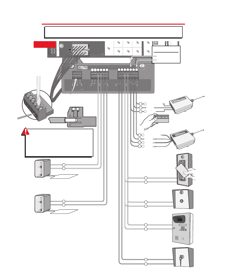
Output Power
Wire
Removable
Terminal
Connectors
Master/Second Link:
Not used in normal
installation
STEP 11
WARNING:
To ENSURE proper operation
of safety devices:
• ENSURE bare wire makes good contact
inside removable terminal connectors.
• DO NOT let wire insulation interfere with
connection.
T E R M I N A L I N P U T C O N N E C T I O N S
Important:
Terminals 11 and 12 are the only terminals that will both Open and/or Close with
a single push of a button. All other terminals will only open with a single push of a button.
13