Installing the system, Preliminary checks, Foundation plate installation – Controlled Products Systems Group 109837 User Manual
Page 9: Mechanical installation
9
FAAC MODEL 844 Slide Gate Operator
2
8 ¾
0 to 2
- Measurements in Inches
2.5
- Measurements in Inches
Fig. 4
Fig. 5
Fig. 7
4.1.
PRELIMINARY CHECKS
To ensure safety and an efficiently operating automated
system, make sure the following conditions are observed:
• The gate structure must be suitable for automation. For
example, wheel diameter must be in proportion to the
weight of the gate to be automated, an upper guide must
be provided, mechanical stop limits to prevent the gate
derailing must be installed.
• The soil must permit sufficient stability for the concrete
pad.
• There must be no pipes or electric cables in the pad
excavation area.
• If the operator is exposed to passing vehicles, install, if
possible, adequate means of protection against acciden-
tal impact.
• Check if an efficient grounding is available for connec-
tion to the gearmotor.
4.2.
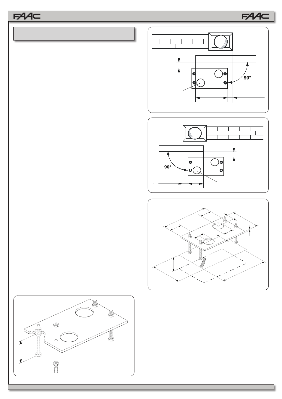
FOUNDATION PLATE INSTALLATION
1. Assemble the foundation plate as shown in Fig 4. The
foundation plate must be located as shown in Fig 5 (right
closing) or Fig 6 (left closing) to ensure that the rack and
pinion mesh correctly.
2. Prepare a concrete pad as shown in Fig.7, following
the suggested dimensions. It’s recommended to have
the pad a minimum of 4” above level grade to avoid any
flooding of the operator. The underground depth of the
concrete pad is determined by the soil condition and
the local building codes. Make sure the concrete pad is
leveled.
3. Provide one or more conduit pathways for all power and
accessory connections. Extend the conduit about of 1/2”
above the level of the concrete pad.
4. After the concrete is poured in the forms and before it
has a chance to set, insert the foundation plate into the
cement and position it flush with the top of the concrete
and aligned with the top of the lower gate frame. Use the
dimensions shown in Figs 5 or 6 to align your founda-
tion plate. Allow the concrete to set for a minimum of two
days before installing the operator.
5. Route the wires in the conduits. To facilitate the connec-
tions allow for about 15” of extra length of cables out of
the conduit. Separate the high and low voltage wires in
different conduits.
1. Assemble the mounting brackets and anti-vibration spac-
ers on the operator as shown in Fig. 8.
2. Open the cover, remove the securing screws.
3. Attach the operator to the plate, using the supplied wash-
ers and nuts as shown in Fig. 9.
4. During this operation, route cables through the opening in-
side the lower half-casing of the operator (Fig.10 - Ref. A).
To access the electronic equipment, route the cables through
the appropriate hole, using the supplied rubber cable-clamp.
Make sure to strip the jacket on all cables so that the clamp
holds single cables only (Fig.10 - Ref. B).
4.
INSTALLING THE SYSTEM
0 to 2
2
6
- Measurements in Inches
Fig. 6
11.5
1.75
1.75
6.25
3
3
2⅜
2⅜
4
7
12.25
0.25
- Measurements in Inches
4.3.
MECHANICAL INSTALLATION