Model 844 operator, Description & specifications – Controlled Products Systems Group 109837 User Manual
Page 7
7
FAAC MODEL 844 Slide Gate Operator
MODEL 844 OPERATOR
These instructions apply to the following models:
844 ER Z16 CR, 844 R, 844 R CAT, 844 R RF
The FAAC Model 844 automated system for sliding
gates is an electro-mechanical operator transmitting
motion to the sliding leaf via a rack or chain pinion
appropriately coupled to the gate.
The non-reversing system ensures the gate is
mechanically locked when the motor is not operating
and, therefore, no lock needs to be installed.
The gearmotor is equipped with a mechanical
clutch which, combined with an electronic device,
offers the necessary adjustable anti-crushing
safety and guarantees stopping or reversing the
gate movement. A handy manual release makes it
possible to move the gate in the event of a power
cut or malfunction. The control board, if supplied
with the gearmotor, it is placed inside the operator.
The 844 automated system was designed and
manufactured to control access of vehicles. Avoid
any other use whatever.
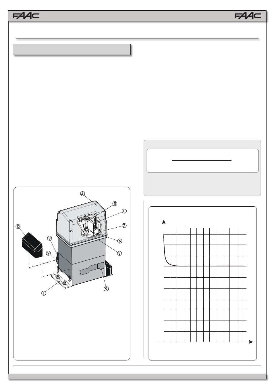
1 Mounting Brackets
2 Pinion
3 Limit Sensor Switch
4 Operator Cover
5 780 D Control Board
6 Adjustment Screw for
Anti-crushing Clutch
7 Oil Filling Plug
8 Operator Grounding
9 Lever Operated Release
System
10 Protective Side Co
11 Cover for 780D Control
Board
Fig. 1
%F =
Ta + Tc
Ta + Tc + Tp + Ti
X 100
Calculation Formula
Where:
Ta = opening time
Tc = closing time
Tp = pause time
Ti = time of interval (between 2 complete cycles)
1.1.
MAXIMUM USE CURVE
The curve makes it possible to establish maximum
work time (T) according to use frequency (F). The
844 gearmotor can operate non-stop at 70% use
frequency.
To ensure efficient operation, operate in the work
range below the curve.
Important: The curve is obtained at a temperature
of 75°F. Exposure to direct sunlight can reduce use
frequency down to 20%.
Calculating Use Frequency
The percentage of effective work time (opening +
closing) compared to total time of cycle (opening +
closing + pause times).
1.
DESCRIPTION & SPECIFICATIONS
0
10
20
30
40
50
60
70
80
90
100
1
2
3
4
5
6
7
8
9 10 11 12
% Freq. Used
% Duty Cycle
Time (h)
Use Frequency Graph