Controlled Products Systems Group 1044182 User Manual
Page 9
P age 9
M a y, 20 06
4 1 5 L LS Ope ra tor A nd
4 5 5 D C ontrol Pa ne l I nsta ll a ti on Ma nua l
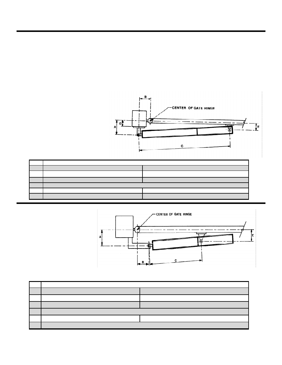
Figure 9. Important mounting
dimensions for inward-swinging
Mounting Dimensions
90-deg Swing
110-deg Swing
A
7 5/8in. (195 mm)
6 5/8 in. (170 mm)
B
7 5/8 in. (195 mm)
6 5/8 in. (170 mm)
C
37 1/8 in. (943 mm)
D
N/A
N/A
E
Less Than A
Figure 10. Important mounting
dimensions for outward-
swinging 415 L LS operators,
top view
Mounting Dimensions
90-deg Swing
110-deg Swing
A
7 5/8 in. (195 mm)
6 5/8 in. (170 mm)
B
7 5/8 in. (195 mm)
6 5/8 in. (170 mm)
C
50 3/4 in. (1290 mm)
D
Maximum 5 in. (125 mm)
4 2/5 in. (110 mm)
E
Less Than A
Less Than A
A
TTACH
THE
O
PERATOR
TO
THE
R
EAR
M
OUNTING
B
RACKET
Attach the rear fork to the 415 L LS operator with the
long steel pin and two “C” clips
Attach the operator to the rear mounting bracket with
the short brass bolt and self locking nut.
A
TTACH
THE
O
PERATOR
TO
THE
F
RONT
M
OUNTING
B
RACKET
Attach the operator to the front mounting bracket with
the short pin and one snap ring on the bottom and one
snap ring on the top.