Assembly, Attach the drive sprocket, Attach mounting brackets – Controlled Products Systems Group 3950 User Manual
Page 5: Assembly step 1, Assembly step 2
5
Operator
Mounting Brackets
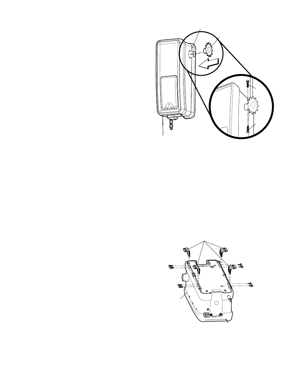
ASSEMBLY STEP 1
Attach the Drive Sprocket
The drive sprocket can be installed on the right or left side of the
operator depending on your installation. The drive sprocket has
three holes to aid in the alignment of the drive sprocket with the
door sprocket.
1. Insert the drive sprocket into the output shaft.
2. Align the center holes in the drive sprocket with the hole in the
output shaft.
3. Insert bolts into the output shaft and the drive sprocket.
4. Finger tighten the bolts.
ASSEMBLY STEP 2
Attach Mounting Brackets
The operator can be mounted to the wall with the mounting
brackets provided. An optional guide mounting bracket is
available for purchase (see accessories).
1. Position two mounting brackets on each side of the operator.
2. Fasten the mounting brackets to the operator using the
self-threading screws (8) provided.
Figure 1
Figure 2
Output Shaft
Drive Sprocket
Bolt
Bolt