Power requirements / power supply specifications, Ower, Equirements – CTI Products MCN RCD System Planner User Manual
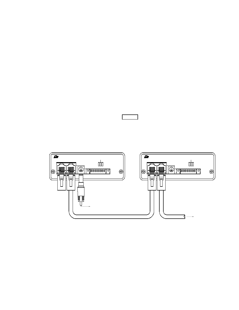
Page 25: Upply, Pecifications, Igure, 12 - dc p, Haining, 4 power requirements / power supply specifications, Figure 12 - dc power chaining
Section 4. System Installation Options
MCN Comparator Display System Planner
Page 21
4.4
Power Requirements / Power Supply Specifications
Power input for all MCN modules is 10 to 32 VDC, with most modules requiring 2 W nominal. AC
power supplies are available that provide 18 VDC at 800 mA. MCN systems have been fully tested for
appropriate immunity to harmful electrical noise and electrical impulses when assembled with these
power supplies. Operation with other, non-qualified power supplies could yield lower system
performance and may void US, Canadian, or European emissions and susceptibility approvals.
The DC IN receptacle of all MCN modules can accept either polarity configuration from the input
power plug.
The MCN system provides a unique way to distribute power to multiple modules from a single power
supply. The network cable used for module communication also contains power lines so that the power
from a power supply can be distributed along with the communication lines. The limits of this power
distribution are the following:
•
A maximum of four modules can be powered from a single power supply.
•
The maximum cable length between the modules that share a power supply is 100 feet.
To create this power distribution (refer to Figure 12), simply connect the power supply into your first
module. Then, connect the NETWORK OUT port of that module to the NETWORK IN port of the
next module. Continue connecting NETWORK OUT ports to NETWORK IN ports until all modules
are connected. If you need to add more power supplies to the system due to power distribution limits,
simply connect another power supply into the DC IN port of a module. This new power supply then
provides power for the module it is connected to as well as all modules from that module’s NETWORK
OUT port or until another power supply is encountered.
CA-80027-100
IN
OUT
NETWORK
PWR
ACT
ERR
DC IN
OPTION A
RESET
SVC
1 2 3 4 5 6 7 8
ON
IN
OUT
NETWORK
PWR
ACT
ERR
DC IN
OPTION A
RESET
SVC
1 2 3 4 5 6 7 8
ON
TO NETWORK IN
OF NEXT MCN MODULE
TO DC POWER SUPPLY
PRODUCTS, INC.
PRODUCTS, INC.
Figure 12 - DC Power Chaining