Alarm, Warning, Auxiliary dc power – CONTREX ML-TRIM User Manual
Page 28
2 - 14
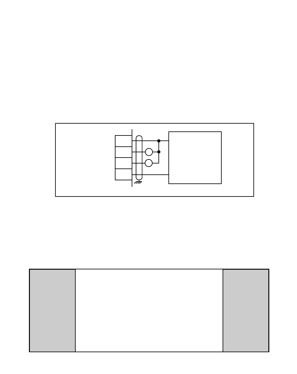
Alarm
(J5 pin 17)
By entering alarm Control Parameters, you can establish circumstances under which
the ML–Trim will alert you to potential operating problems. The alarm can be wired to
activate a warning light, a warning sound, or to shut down the system under specified
conditions. Alarm Format (CP-10) determines which alarm conditions will activate the
Alarm output, using the values that are entered in Low Alarm (CP-12), High Alarm
(CP-13), Ramped Error (CP-14) and Scaled Error (CP-15). See Figure 2-15. Refer to
Operations: Logic Control, Logic Output,
page 3-37 for details.
NOTE: This is an open-collector relay driver. Use an external DC power supply to
power the relays. Free-wheeling diodes are incorporated internally in the
ML–Trim and do not need to be added externally.
15
16
17
18
J5
EXTERNAL
DC
POWER
SUPPLY
(50V Max)
+V_DO
Drive Enable
Alarm
Common
+
–
R1
R2
WARNING
Do not exceed
the maximum current output of
150 mA for +5 VDC.
Exceeding the maximum
current output
can damage the ML–Trim.
Figure 2-15 Drive Enable and Alarm Outputs
Auxiliary DC Power
(J4 pin 1, 2)
The 5 volt output (J4 pin 1) is a DC regulated output that can be used to power
encoders or other auxiliary equipment that is used in conjunction with the ML–Trim. If
this output is used, it will nullify optical isolation.