Inputs, Inputs -7, I/o power (j5 pins 1, 2) – CONTREX ML-TRIM User Manual
Page 21
2 - 7
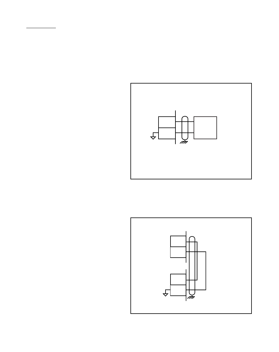
Figure 2-3 I/O Power / Isolated
Figure 2-4 I/O Power / Non-Isolated
INPUTS
NOTE: The installation of this motor control must conform to area and local electrical
codes. See
The National Electrical Code
(NEC,) Article 430 published by the
National Fire Protection Association, or
The Canadian Electrical Code
(CEC).
Use local codes as applicable.
I/O Power (J5 pins 1, 2)
For isolated operations, the
Frequency Inputs (J5 pins 3, 4, 5),
the Digital Inputs (J5 pins 6-14 ) and
the Digital Outputs (J5 pins 15-18)
require an external source of
+5VDC power.
CAUTION: The ML-Trim is
shipped from the factory non-
isolated with J4 and J5 jumpers.
You must remove the J4 and J5
jumpers before you connect the
External Power supply or you can
damage the equipment. Do not
exceed +5VDC on the I/O Power
Input.
Use the Auxiliary Power Output
(J4 pins 1, 2) to supply power to
non-isolated operations. The
ML-Trim is shipped from the factory
with the wiring defaulted to the non-
isolated operation.
+5VDC
External
Power
Supply
1
2
J5
+5V
COM
1
2
J5
1
2
J4
COM_AUX
+5V
+5VDC MAXIMUM
* Do not connect the External Power Supply
Common to Earth Ground.
*