Chapin 61500 User Manual
Page 10
2) Remove the retaining pin (A) (Figure 2) place the notched
end of the retaining pin on a hard surface and push down.
Remove the retaining pin and slide the handle off the valve.
A
Figure 2
9E
Tube
Robinet
d'arrêt
Joint torique
Écrou de blocage
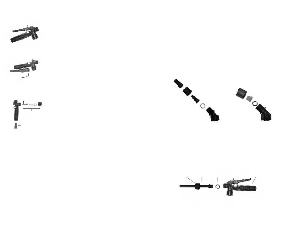
ASSEMBLAGE DE LA BUSE
Figure 1
Dévissez le bouchon de la buse (1) du corps de la buse (3) tandis que l’écrou de blocage (2) est bien
installé au coude (5). Dévissez l’écrou de blocage (2). Poussez le corps de la buse (3) avec le joint de buse
(4) hors de l’écrou de blocage (2). Pour réinstaller la buse, inversez les instructions précédentes.
Figure 2
Dévissez l’écrou de blocage du coude et poussez l’embout de buse en éventail et le joint d’étanchéité hors de
l’écrou de blocage. Pour réinstaller la buse, inversez les instructions précédentes.
2F
3. Corps de buse
2. Écrou de blocage
5. Coude
4. Joint de buse
Figure 1
1. Bouchon de
buse de poly
Figure 2
Coude
Joint de buse
Embout de buse
en éventail
Écrou de blocage
INFORMATION D’UTILISATION ET DE COMPOSANTS DU PULVÉRISATEUR
ASSEMBLAGE DE TUBE
1. Assurez-vous que le joint torique soit installé à l’extrémité du tube. Insérez le tube dans le
robinet d’arrêt.
2. Tournez et resserrez l’écrou de blocage dans le sens horaire sur le robinet d’arrêt.
DISASSEMBLING AND REPAIRING THE SHUT OFF VALVE
1) Assembled shut-off valve (Figure 1).
Figure 1
3) Remove the retaining nut (o-ring attached), spring, and valve stem (B)
(Figure 3). Replace worn parts. Lubricate the O-rings and reassemble by
reversing the steps above. Place the handle groove in the slotted area of
the valve stem and make sure the locking clip is positioned in the neutral
position (see “Helpful Spraying Information” section). Insert the retaining
pin. Push down on the handle a few times to distribute the lubricant
evenly. Check filter (C) in end of shut-off valve for debris. Remove filter
and flush with water to clean out.
Figure 3
C
Valve
Stem
B