Ection, Tech tips, Frequency interaction – Clear-Com WTR-670 User Manual
Page 48: Microphone gain adjustment
Tech Tips
Frequency Interaction
Unfortunately, radio frequency (RF) channels cannot be ran-
domly selected for use in radio devices. They must be selected
to avoid known frequencies in use, FCC restrictions on the lo-
cation of devices, and even interference between your own RF
devices. The factory defined frequencies (Groups 01A-24) se-
lected for this system are chosen to minimize possible interfer-
ence.
Microphone Gain Adjustment
The microphone gain controls on the base station and beltpack
are set to mid-levels by the factory. In most cases this setting
will work fine and only on loud speech will the
overmodulation (OM) indicator light. However, in environ-
ments where the background noise is loud or the user has a
strong/quiet voice, the gain control will need to be adjusted. In
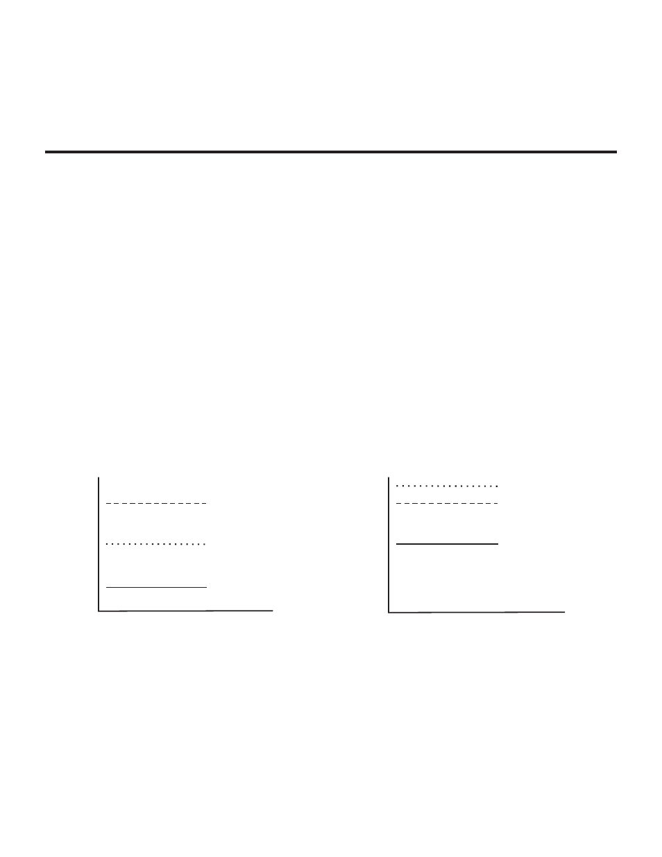
Figure22 the gain is set correctly. The user’s root-mean-square
(RMS) sound level is well below the OM threshold and only
on peaks does his or her voice flash the OM indicator light.
Figure 23 displays the same gain setting as in Figure 22 but
brought into a high noise environment. The user’s voice now
lights the OM indicator all the time he or she speaks due to the
higher noise plus the user speaking louder. The result on the
system is distortion on louder speech. The microphone gain
must be reduced. The same applies to a user with a powerful
voice. If someone sets the system mic gain to their voice and
user has a much stronger voice, then the gain will need to be
reduced, even if the background noise is the same.
Always remember to set the microphone gain based on the sit-
uation and location in which the equipment will be used. If the
equipment is used on the field during a football game, set the
gain based upon a loud stadium, NOT the quiet stadium 2
hours before a game. If a production studio user has a quiet
voice, set the gain to their voice and NOT the stage hand’s
loud voice who helped set up the system.
9-1
OM THRESHOLD
USER'S VOICE
NOISE
SOUND
LEVEL,
R
MS
OM THRESHOLD
USER'S VOICE
NOISE
SOUND
LEVEL,
R
MS
Figure 22
Low Noise Environment
Microphone Gain Set Correctly
Figure 23
High Noise Environment
Microphone Gain Set Too High
S
ection
9