Antenna connection, Antenna polarization, Distance between antennas – Clear-Com WTR-670 User Manual
Page 16: Antenna placement
Antenna Connection
The base station is supplied with two (2) antennas. One
1/2-wave antenna for Transmit and one 1/2-wave for Receive.
The antennas have TNC male connectors.
The frequency range of the antennas should match the receiver
and transmitter of the base station. Match the color code on
the antenna with the color code on the base station.
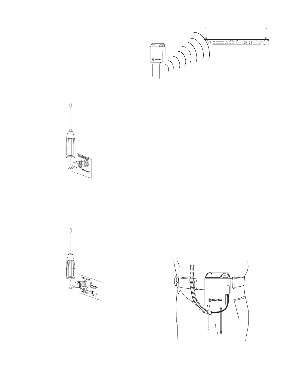
Attach the transmit 1/2-wave antenna to the antenna input re-
ceptacle labeled “Transmit” on the right side of the rear panel.
The antenna should be vertically aligned.
Figure 7
Attaching Transmit 1/2-Wave Antenna
Attach the receive 1/2-wave antenna to the antenna input re-
ceptacle labeled “Receive” on the left side of the rear panel.
The antenna should be vertically aligned.
Figure 8
Attaching Receive 1/2-Wave Antenna
Antenna Polarization
The Clear-Com
®
Wireless Intercom System is “Vertically Po-
larized”. This means both the transmitting and receiving an-
tennas should operate in the vertical position.
Figure 9
Vertically Polarized Antennas
Distance between Antennas
The distance between the base station’s receive and transmit
antennas is not adjustable when the antennas are connected di-
rectly on the back of the unit.
The antennas can be remoted for better signal path.
NOTE: If your base station is to be located in a shielded rack
mount enclosure or other poor RF location, you must remote
the 1/2-wave antennas.
Antenna Placement
Proper antenna placement probably has the most effect on
your Clear-Com
®
Wireless Intercom System’s overall perfor-
mance. The following suggestions will result in optimum per-
formance.
Proper placement of the beltpack can be critical. The antennas
should be in the open. Bending the antennas up and placing
the beltpack in a pocket, etc., will reduce system distance.
It is suggested that the unit be worn on the belt or pocket with
both antenna’s vertical for best operating range and perfor-
mance.
Figure 10
Proper Dressing of the Antennas
4-2
TELEX
CLEAR
COM
T e
le
x
OF
F
BA
T/O
M
T A
LK
VOL
WTR-670
Gain
Volume
On/Off
In
Out
AUXILIARY
2-Wire
4-Wire
Select
In
Out
BELTPACK CONNECT
1
2
3
4
Up
Down
Menu
Set
SCAN
INTERCOM
WBS-670
Copy
TALK
ANTENNAS SHOULD BE VERTICAL
T e
le
x
OF
F
BA
T/O
M
T A
LK
VOL
WTR-670