System fault and alarm indication, Functions, Real time clock setup – Fluid Components International ST100 Series User Manual
Page 22
INSTALLATION
ST100 Series Flow Meter
18
Fluid Components International LLC
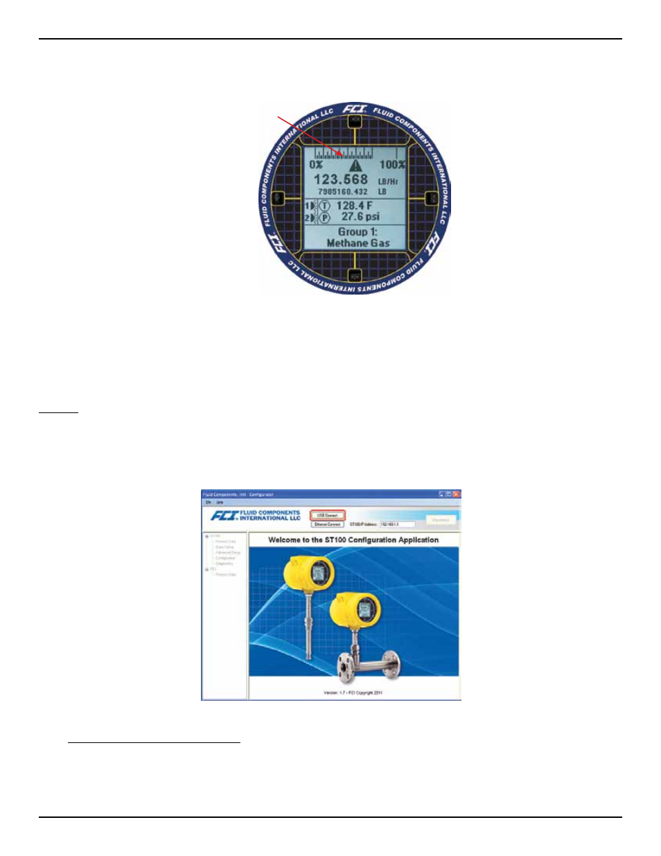
System Fault and Alarm Indication
The ST100 LCD Display indicates both alarm and fault conditions with a caution triangle icon directly above the flow rate indication on the
LCD.
Fault/Alarm Icon
When an alarm condition is met, the indicator will flash on and off. The flashing condition will continue until the alarm condition no longer
exists or the alarm is acknowledged using the HMI display menu. The alarm indicator can also be turned off by disabling the condition
through the configurator alarm Tab.
Instrument fault codes can be viewed by selecting the Diagnostics branch in the configurator tree or the HMI display menu.
Functions
Real Time Clock Setup
The ST100 clock reset function is accessed via the ST100 Configurator. Reference the ST100 Configuration supplemental manual for installa-
tion instructions, FCI document number 06EN003403. The Configuration program is installed on a PC or Laptop computer and can be con-
nected via the USB or Ethernet. The USB is the primary mode of communication with the ST100.
Welcome Screen
To access the ST100 Clock Reset Function: 2
1. Connect a USB cable between the computer with the Configuration Application installed and the USB connection on the interface board.
2. Select the ST100 Configurator icon to open the application. The application will open to the welcome screen as shown above.
3. Select the USB Connect button at the top of the screen. The Configuration application will open to the Process Data screen as shown
below.