Troubleshooting, In-line sensor installation, Flow transmitter electronics installation – Fluid Components International ST100 Series User Manual
Page 15: Integral electronics
ST100 Series Flow Meter
INSTALLATION
Fluid Components International LLC
11
Troubleshooting
The “Service Mode” both HART and F
oundation
fieldbus provide access to the individual sensor output values.
The ST/STP102A electronics transmitter can recognize a disconnected flow element. If this condition is detected, the instrument will indicate
a fault condition and display process variables from the sensor that remains connected to the transmitter. The fault will self-correct when the
sensor is re-connected.
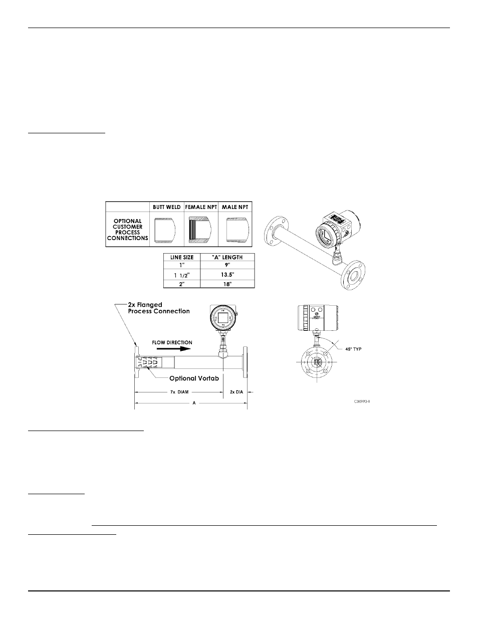
In-Line Sensor Installation
The sensor can be threaded, flanged or butt weld mounted to the process piping. The specific sensor process connection is customer specified on the
Order Information Sheet.
Mount the sensor to the process piping per the application piping requirements. Verify the flow direction arrow is pointed in the correct direction.
After the sensor head has been located correctly and tightened into place, verify the process seal does not leak by slowly applying pressure until the
normal operation pressure is applied. Check for leaks at the process connection boundary.
Flow Transmitter Electronics Installation
The instrument electronic transmitter can be an integral part of the flow element or it can be mounted remotely using a shielded cable between the
flow element and the electronics.
Supply connection wiring must be rated at least 90 °C.
Integral Electronics
The integral electronics package is mounted during the flow element installation process. The integral electronics can be rotated +/- 180 degrees
on the top of the flow element insertion pipe. This is done by loosening the lock nut at the base of the enclosure and rotating the enclosure to the
preferred orientation. Do not rotate the electronics enclosure more than +/- 180 degrees, damage to internal wiring may result from
over rotating the enclosure!
Lock Nut Torque Specification: 30-35 ft-lbs (40-47 N-m)
The Integral electronics should be supported in applications where excessive vibration is present. A mounting bracket is available from FCI to sup-
port the electronics when additional support is required.
Figure 5