Post installation check, Basic commissioning and start-up – Fluid Components International ST100 Series User Manual
Page 19
ST100 Series Flow Meter
INSTALLATION
Fluid Components International LLC
15
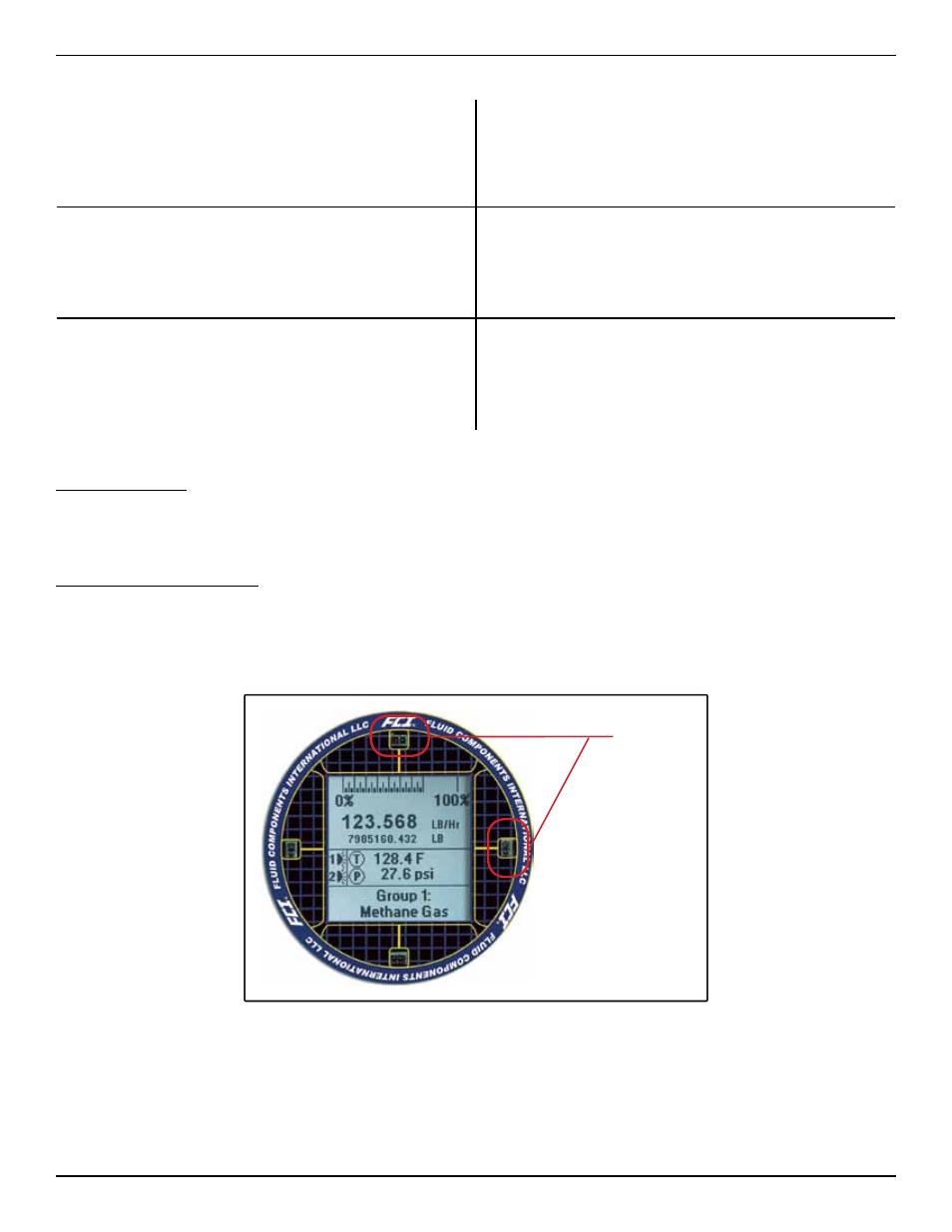
The instrument LCD display functions as a basic HMI setup tool. The four buttons (IR sensors) located at the 3, 6, 9 and 12 o’clock positions on the
display provide access to the basic setup parameters. The screen flow is shown in figure 18. The HMI setup menu can be accessed thru the window
without removing the electronics enclosure lids. This is done by holding your finger in front of the 12 o’clock sensor for 3 seconds. The LCD acknowl-
edges the button selection by inverting the display characters and background while the button is held.
Reference the following wiring diagrams in Appendix B for specific integral and remote mounted electronics.
Figure B-1 : Integral - AC Input Power, Analog and HART Output
Figure B-2 : Remote - AC Input Power, Analog and HART Output
Figure B-3 : Integral - DC Input Power, Analog and HART Output
Figure B-4 : Remote - DC Input Power, Analog and HART Output
Figure B-9 : Integral - AC Input Power, Modbus Output
Figure B-10 : Remote - AC Input Power, Modbus Output
Figure B-11 : Integral - DC Input Power, Modbus Output
Figure B-12 : Remote - DC Input Power, Modbus Output
Figure B-5 : Integral - AC Input Power, F
oundation
fieldbus Output
Figure B-6 : Remote - AC Input Power, F
oundation
fieldbus Output
Figure B-7 : Integral - DC Input Power, F
oundation
fieldbus Output
Figure B-8 : Remote - DC Input Power, F
oundation
fieldbus Output
Figure B-13 : Remote - 8 Conductor Interconnection Cable
Figure B-14 : Source - Pulse/Fequency Output
Figure B-15 : Sink - Pulse/Fequency Output
ST102/STP102
Figure B-16 : Flow Element Connection - Integral/Remote
Figure B-17 : Flow Element Connection - Remote
STP100/STP102
Figure B-18 : Remote - 10 Conductor Interconnection Cable
Post Installation Check
Verify all wiring connections are secure and correct to the appropriate wiring diagram. Verify the flow direction arrow on the flow element is pointing
in the correct direction. Verify the mechanical process connection is secure and meets the system pressure requirements.
Basic Commissioning and Start-Up
When all wiring and process connections have been verified, apply power to the instrument. The instruments with the LCD will briefly show a
welcome screen indicating the software version followed by the normal operation process screen. The normal process screen indicates process flow
rate, total flow, temperature and pressure depending on the options ordered. The calibration group and group description are also displayed at the
bottom of the screen. Verify the process variable engineering units are correct.
Normal Operation Process Screen
I.R. Sensors
(4 places)