Fluid Components International MT91 Manual Operation User Manual
Page 10
FLUID COMPONENTS INTL
CHAPTER 3 - OPERATION
Model MT91 Multipoint Flowmeter
3 - 10
Doc. No. 003185 Rev. B
Ø To calibrate the analog output boards:
The analog output board calibration parameters are saved on the controller board. Therefore, analog output boards
are not interchangeable.
Tools needed:
DVM (4 1/2 digit minimum)
Calibrated 250
W
resistor
1.
Turn off the power to the flowmeter.
2.
Set both jumpers on the analog output board to the output type selected above.
3.
Connect a DVM to the appropriate connection of the analog output board. Use a precision 250ohm resistor if
the output is 4 to 20mA.
4.
Apply power to the flowmeter.
5.
Go to menu level 2.2.2 (Setup
Þ
Outputs
Þ
Analog). Select the Channel 1. Press 1 to select output signal.
6.
Select appropriate signal type. Save selection if signal type was changed.
7.
Go to menu level 4.3.1 (Calibration
Þ
CalOutputs
Þ
Analog Outputs). Select Channel 1.
8.
Press keys as indicated to reach 4mA for 4-20mA output signal or press ENTR (0) for 0-5Vdc output signal and
0-10Vdc output signal.
Note:
The DVM may read 20-30mV for 0-10Vdc output signal or 10-15mV for 0-5Vdc output signal.
9.
Press keys as indicated to reach 20mA for 4-20mA output signal or press keys as indicated to reach 5.000Vdc
for 0-5Vdc output signal or press keys as indicated to reach 10.00Vdc for 0-10Vdc output signal.
10. Repeat steps 5 through 9 for Channel 2.
Setting Discrete Outputs
Four sets of relay contacts provide the user with discrete outputs. The relays can be assigned to the parameters
marked in Table 3-3.
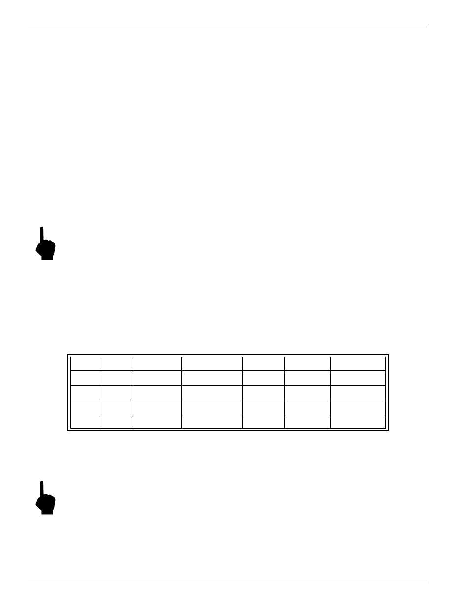
Table 3-3. Relay Assignment by Parameters
Relay #
Flow
Temperature Calibration Test
Zero Test
Span Test
System Status
1
♦
♦
•
•
•
•
2
♦
♦
•
•
•
•
3
•
•
•
•
4
•
•
•
•
♦
Dependent on analog outputs
Ø To set discrete outputs
1.
Go to menu level 2.2.3.1 (Setup
Þ
Outputs
Þ
Relays
Þ
Mode)
2.
Select the relay to be set: 1=Rly #1, 2=Rly #2, 3=Rly #3, or 4=Rly #4.
Note:
Only relays 1 and 2 can be set as switch points.