Wiring remote enclosure with auxiliary relay, Wiring the remote enclsoure – Fluid Components International FLT93 Nuclear User Manual
Page 15
FLT
®
Series FlexSwitch
TM
INSTALLATION
Fluid Components International LLC
15
Wiring the Local Enclosure
This procedure is for instruments with the control circuit located in the sensing element enclosure.
1. Remove the control circuit from its socket. Do not remove the control circuit socket. Removal of the control circuit socket may cause
damage to the instrument.
2. Install conduit between the local enclosure and the power source and monitoring circuit. Provide watertight hardware and apply thread
sealant to all connections to prevent water damage.
Warning: Ensure that all power is off before wiring any circuit.
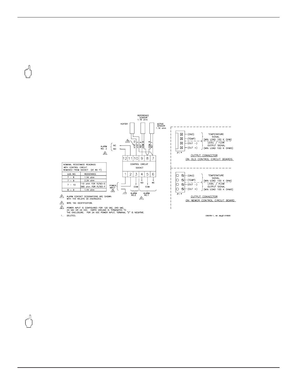
3. When connecting the relay wiring, do so with complete understanding of what the process requires of the instrument. The instrument
has dual SPDT or single DPDT relay output contacts dependent on the jumper confi guration for each alarm switch point. For the relay
logic, refer to Figure 2-5. Also refer to Table 3-5 and Table 3-6 in Chapter 3 - Operation. Relay contacts are shown with the relays de-
energized. Wire in accordance with the system requirements.
Figure 2-5 Local Wiring Diagram
Wiring the Remote Enclosure
This procedure is for instruments with the control circuit located remotely from the sensing element.
Locate the Remote Hardware Location
Select a location for the remote enclosure within a 1000 feet (305 m) of the sensing element. Pigtail sensing elements can not be located
more than 10 feet (3 m) from the enclosure unless the pigtail is extended with the proper size cable listed in Table 2-1. If the cable is ex-
tended the cable connections should be located in a junction box with a 6 position terminal block. All 5 conductors and the shield must have
its own termination. The remote enclosure should be easily accessible with enough room to open the enclosure cabinet cover at any time.
Secure the remote enclosure solidly to a vertical surface capable of providing support. Use appropriate hardware to secure the enclosure.
1. Remove the control circuit from the remote enclosure.
2. Run a fi ve-conductor, shielded cable from the local enclosure to the remote enclosure. Use Table 2-1 to determine which wire gauge to
use.
3. Wire between the local and remote enclosures according to Figure 2-6.
Warning:
Ensure that all power is off before wiring any circuit.
4. When connecting the relay wiring, do so with complete understanding of what the process requires of the instrument. The instrument
has dual SPDT or single DPDT relay output contacts dependent on the jumper confi guration for each alarm switch point. For the relay
logic, refer to Figure 2-6. Also refer to Table 3-5 and Table 3-6 in Chapter 3 - Operation. Relay contacts are shown with the relays de-
energized. Wire in accordance with the system requirements.