English, Fig. 34: wiring of the do2 and do3 relay outputs – Burkert Type 8035 User Manual
Page 44
42
Installationandwiring
Type 8025 /8035 Batch
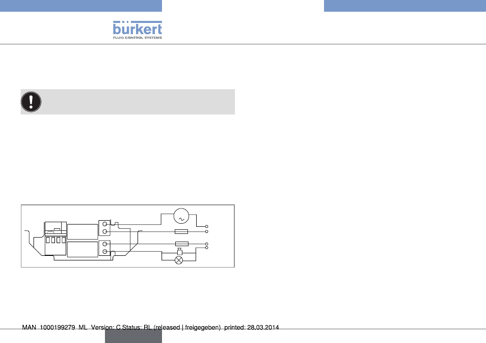
7.6.12 Wiring the relay outputs Do2 and
Do3 of a compact, a panel-mounted
or a wall-mounted version
To▶carry▶out▶a▶dosing,▶connect▶a▶valve▶to▶the▶relay▶output▶
DO2.
The▶device▶can▶control:
•▶ either▶a▶dosing▶with▶a▶single▶valve▶connected▶to▶the▶relay▶output▶
DO2.
•▶ or▶a▶dosing▶with▶2▶valves▶connected▶to▶the▶relay▶outputs▶DO2▶and▶
DO3.▶In▶this▶case,▶connect▶the▶main▶valve▶(for▶the▶highest▶flow▶
rates)▶to▶output▶DO2▶and▶the▶auxiliary▶valve▶(for▶low▶flow▶rates)▶to▶
output▶DO3.
If▶a▶single▶valve▶is▶used,▶connect▶a▶load▶to▶relay▶output▶DO3▶suited▶
for▶the▶configuration▶of▶the▶output.
FLOW
SENSOR
SUPPLY
NC
COIL
PULSE INPUT
NPN/PN
P
2
1
3
PE
+
-
DO2
DO3
OF
FO
N
230 V AC
m
3 A
3 A
230 V AC
Fig. 34: Wiring of the DO2 and DO3 relay outputs
▶
→
To▶configure▶the▶relay▶output▶DO2,▶Refer▶to▶the▶detailed▶oper-
ating▶instructions.
▶
→
To▶configure▶the▶relay▶output▶DO3,▶Refer▶to▶the▶detailed▶oper-
ating▶instructions.
English