Burkert Type 8055 User Manual
Page 18
SE 56
18
210_EN_BU_4_3_5X.d
oc
M1
M3
1
2 3 4 5 6 7 8 9 10
11 12 13 14 15 16 17 18 19 20
LOCK
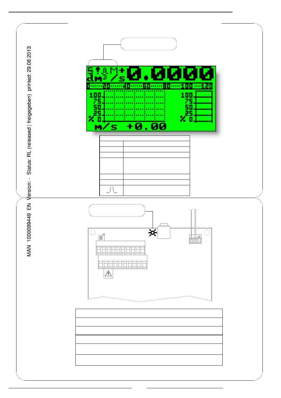
INTERPRETATION FLAGS
FLAG
DESCRIPTION
M
Alarm max activated
m
Alarm min activated
!
- Interruption coils circuit
- Segnal error
- Empty pipe
C
Calibration running
S
Simulation
Pulse output saturation (
reduce TIME PULSE )
Flags interpretation and LED
FLAGS
LED
LED INTERPRETATION
PERMANENT LIGHT: initialisation
FLASHING LIGHT ( 1 sec.): normal function
FLASHING LIGHT (<1 SEC.): alarm on
The LED signals the real alarm status only if the display visualizes one of
the visualization pages suitable to page 17
ATTENTION: in the panel version the LED is not visible
This manual is related to the following products: