Electrical installation devicenet – Burkert Type 8695 User Manual
Page 20
20
Electricalinstallation/displayelements
9.7 electrical installation Devicenet
9.7.1 Bus connection (circular connector
m12 x 1, 5-pole, male)
The control head features a 5-pole micro-style circular connector.
The following configuration conforms to the DeviceNet specification.
→
Connect the control head according to the table.
pin
1
2
3
4
5
signal
Shielding V +
V –
CAN_H
CAN_L
Tab. 8: Pin assignment circular plug-in connector DeviceNet
Pin 4: CAN_H
white
Pin 5: CAN_L
blue
Pin 1: Drain
(Shield)
Pin 3: V–
black
Pin 2: V+
red
Data lines
Supply voltage
11 – 25 V DC
max. power 3 W,
if valve is switched
Fig. 15: View of plug from the front onto the pins, the soldered connections
are behind
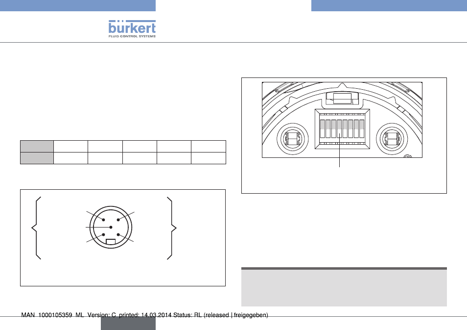
9.7.2 configuring the control head
setting the Dip switches
DIP switches for bus address
and baudrate
1 2 3 4 5 6 7 8
OFF
Fig. 16: DIP switches DeviceNet
8 DIP switches are available for configuration:
• DIP switches 1 to 6
for the DeviceNet address
• DIP switches 7 to 8
for the baudrate
procedure:
note!
Breakage of the pneumatic connection pieces due to rota-
tional impact.
▶ When unscrewing and screwing in the transparent cap, do not
hold the actuator of the process valve but the connection housing.
english
Type 8695