Of series 20xx – Burkert Type 8695 User Manual
Page 12
12
Installation
→
Push the control head, without turning it, onto the actuator until
no gap is visible on the form seal.
note!
too high torque when screwing in the fastening screw does
not ensure protection class ip65 / ip67.
▶ The fastening screws may be tightened to a maximum torque of
0.5 Nm only.
→
Attach the control head to the actuator using the two side fas-
tening screws. In doing so, tighten the screws only hand-tight
(max. torque: 0.5 Nm).
Connection
pieces
Pilot air
ports
(actuator)
Fastening
screws
max. 0.5 Nm
Fig. 5:
Installation of control head, 21xx series
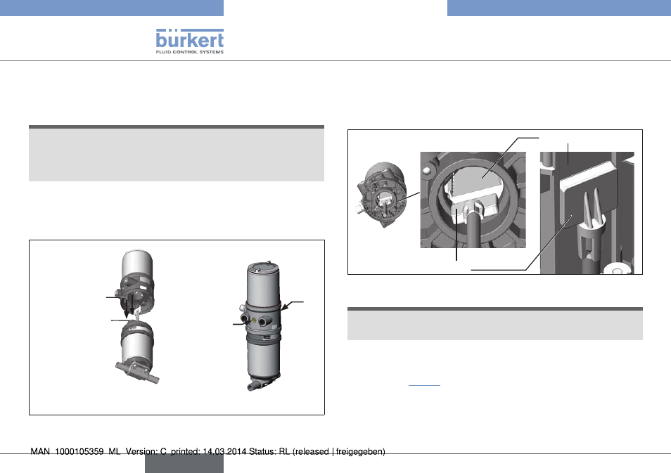
7.3 installation of the control head on
process valves of series 20xx
Procedure:
Guide rail
Puck
Fig. 6:
Aligning the puck
note!
damaged printed circuit board or malfunction.
▶ Ensure that the puck is situated flat on the guide rail.
→
Push the control head onto the actuator. The puck must be aligned
in such a way that it is inserted into the guide rail of the control
head (see “Fig. 6”).
→
Press the control head all the way down as far as the actuator
and turn it into the required position.
english
Type 8695