9 electrical installation / display elements – Burkert Type 8695 User Manual
Page 15
15
Electricalinstallation/displayelements
Important information for the problem-free functioning of
the device:
▶ The installation must not cause back pressure to build up.
▶ Select a hose for the connection with an adequate
cross-section.
▶ The exhaust air line must be designed in such a way that
no water or other liquid can get into the device through the
exhaust air port.
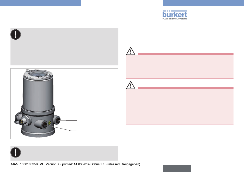
Pilot air port
(label: 1)
Exhaust air port
(label: 3)
Fig. 8:
Pneumatic connection
Caution:
(Exhaust air concept):
In compliance with protection class IP67, an exhaust air line
must be installed in the dry area.
9
elecTrical insTallaTion /
Display elemenTs
9.1 safety instructions
Danger!
risk of electric shock.
▶ Before working on equipment or device, switch off the power
supply and secure to prevent reactivation.
▶ Observe applicable accident prevention and safety regulations
for electrical equipment.
Warning!
risk of injury from improper installation.
▶ Installation may be carried out by authorized technicians only
and with the appropriate tools.
risk of injury from unintentional activation of the system and
an uncontrolled restart.
▶ Secure system from unintentional activation.
▶ Following installation, ensure a controlled restart.
9.2 electrical installation 24 V Dc
→
Connect the control head according to the table.
The teach function can now be used to automatically determine
and read in the end positions of the valve (description of the teach
function see chapter “10 Teach function”).
english
Type 8695