4 electrical installation as-interface – Burkert Type 8695 User Manual
Page 17
17
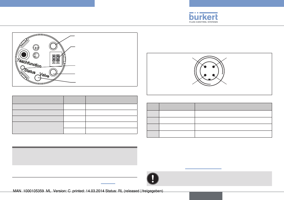
Electricalinstallation/displayelements
ye
gn
Bo
t
To
p
To
p
Bo
t
ye
gn
Jumper for assignment of
end position LEDs
End position LED green
End position LED yellow
Valve LED yellow (pilot valve)
Status LED yellow
Fig. 11: Display elements 24 V DC
led
state
End position LED green
on
End position bottom
2)
End position LED yellow
on
End position top
2)
LED Valve yellow
on
Pilot valve is actuated
Status LED yellow
flashing
Teach function is running
flickers
Puck PCB not available
Tab. 3: Display elements 24 V DC
note!
damage or malfunction due to penetration of dirt and humidity.
▶ To observe protection class IP65 / IP67, screw the transparent
cap in all the way.
2)
Color setting ex works. Can be set via jumper (see “Fig. 11”).
9.4 electrical installation as-interface
9.4.1 connection with circular plug-in
connector m12 x 1, 4-pole, male
Pin 4:
NC
Pin 1:
Bus +
Pin 3:
Bus –
Pin 2:
NC
Fig. 12: Connection with circular plug-in connector, AS-Interface
pin
designation
configuration
1
Bus +
AS-Interface bus line +
2
NC
not used
3
Bus –
AS-Interface bus line -
4
NC
not used
Tab. 4: Pin assignment of circular plug-in connector for AS-Interface
→
Connect the control head according to the table.
The teach function can now be used to automatically determine
and read in the end positions of the valve (description of the teach
function see chapter “10 Teach function”).
For the bus variant AS-Interface, the teach function can also
be started via the bus protocol.
english
Type 8695