Burkert Type 8695 User Manual
Page 13
13
Installation
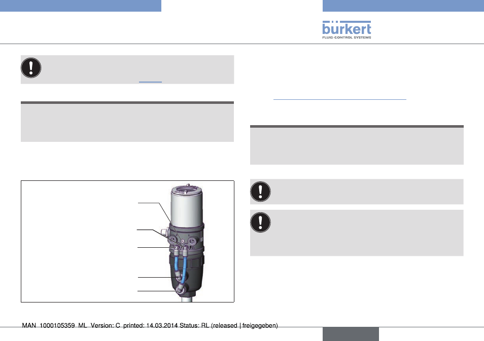
Ensure that the pneumatic connections of the control head
and those of the valve actuator are situated preferably verti-
cally one above the other (see “Fig. 7”).
note!
too high torque when screwing in the fastening screw does
not ensure protection class ip65 / ip67.
▶ The fastening screws may be tightened to a maximum torque of
0.5 Nm only.
→
Attach the control head to the actuator using the two side fas-
tening screws. In doing so, tighten the fastening screws hand-
tight only (maximum torque: 0.5 Nm).
Pilot air outlet 2
1
Pilot air outlet 2
2
Upper pilot air port
Lower pilot air port
Fastening screws (2x)
Fig. 7:
Installing the pneumatic connection, 20xx series
→
Screw the plug-in hose connectors onto the control head and
the actuator.
→
Using the hoses supplied in the accessory kit, make the pneu-
matic connection between the control head and actuator with
the “Tab. 1: Pneumatic connection to actuator”.
note!
damage or malfunction due to ingress of dirt and moisture.
▶ To comply with protection class IP65 / IP67, connect the pilot
air outlet
(only for CFA or CFB) which is not required to the free
pilot air port of the actuator or seal with a plug.
“In rest position” means that the pilot valves of the control
head Type 8695 are isolated or not actuated.
If the ambient air is humid, a hose can be connected between
pilot air outlet 2
2
of the control head and the unconnected
pilot air port of the actuator for control function A or control
function B. As a result, the spring chamber of the actuator is
supplied with dry air from the vent duct of the control head.
english
Type 8695