On process valves of series 20xx – Burkert Type 8690 User Manual
Page 18
18
Installation
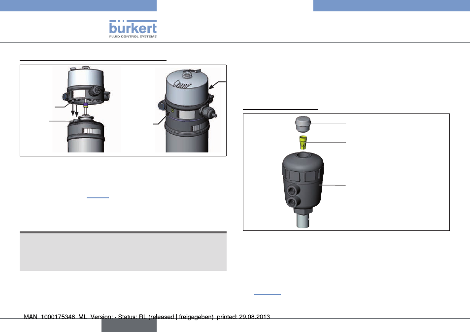
3. installation of the pneumatic control unit:
Supports
Pilot air
ports
Fastening
screws
max. 0,5 Nm
Fig. 9: Installation of the Pneumatic Control Unit, 21xx series
→
Align the Pneumatic Control Unit until the supports of the Pneu-
matic Control Unit can be inserted into the pilot air ports of the
actuator (see also “Fig. 9”).
→
Push the Pneumatic Control Unit, without turning it, onto the
actuator until no gap is visible on the form seal.
noTE!
too high torque when screwing in the fastening screw does
not ensure protection class ip65 / ip67!
• The fastening screws may be tightened to a maximum torque of
0.5 Nm only.
→
Attach the Pneumatic Control Unit to the actuator using the two
side fastening screws. In doing so, tighten the screws only hand-
tight (max. torque: 0.5 Nm).
7.3.
installation of the pneumatic
control unit Type 8690 on
process valves of series 20xx
procedure:
1. install switch spindle
Transparent cap
Position indicator
Actuator
Fig. 10: Installation of the switch spindle (1), series 20xx
→
Unscrew the transparent cap on the actuator.
→
Using a hexagon socket key, unscrew the orange/yellow position
indicator from the inside of the actuator.
→
Press the O-ring downwards into the cover of the actuator (see
“Fig. 11”).
english
Type 8690 Ex