English, 2 setting the station addresses, 3 led display – Burkert Type 8642 User Manual
Page 14: 4 watchdog, 5 gsd file
12 - 8642/142 791
english
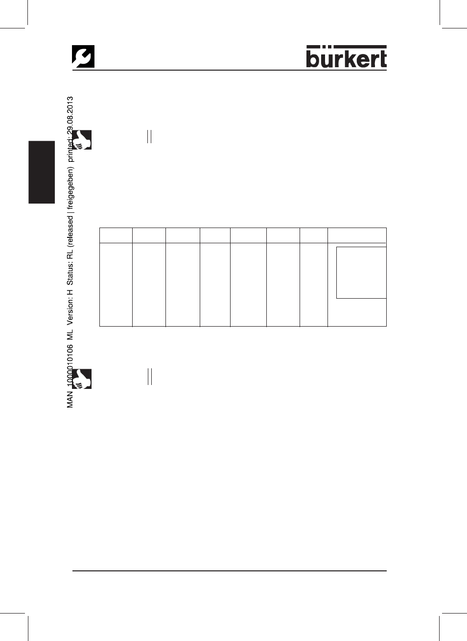
4.2.2 Setting the Station Addresses
DIP switch 1 to 7
Bit 1 to Bit 7
NOTE
The DIP switches are only read in when the unit is switched on.
In the PROFIBUS-PA, each station is given an address. These addresses are
set
up using the DIP switches 1 to 7.
The permissible address range lies between 3 and 124
4.2.3 LED Display
The LED lights up when the unit is in cyclic data traffic.
4.2.4 Watchdog
In order to detect errors better, we recommend to operate the device in the
cyclic data communication with "DP watchdog".
4.2.5 GSD file
Use the GSD file Buer6521.GSD, which is to be found under the ID no. 142791
on the enclosed data memory. The associated bitmaps are also there.
Settings:
DIP-1
DIP-2
DIP-3
DIP-4
DIP-5
DIP-6
DIP-7 Address
ON
ON
OFF
OFF
OFF
OFF
OFF
3
..
OFF
OFF
ON
ON
ON
ON
ON
124
ON
OFF
ON
ON
ON
ON
ON
125
OFF
ON
ON
ON
ON
ON
ON
126*
* Delivery state: Address 126
permitted address
range
3 ... 124
DIP switches 9 - 12 are not used.
NOTE
If switch 8 is in the ON position, the internal address is used!
This address can be set up via the field bus.