Burkert Type 2037 User Manual
Page 10
10
Assembly
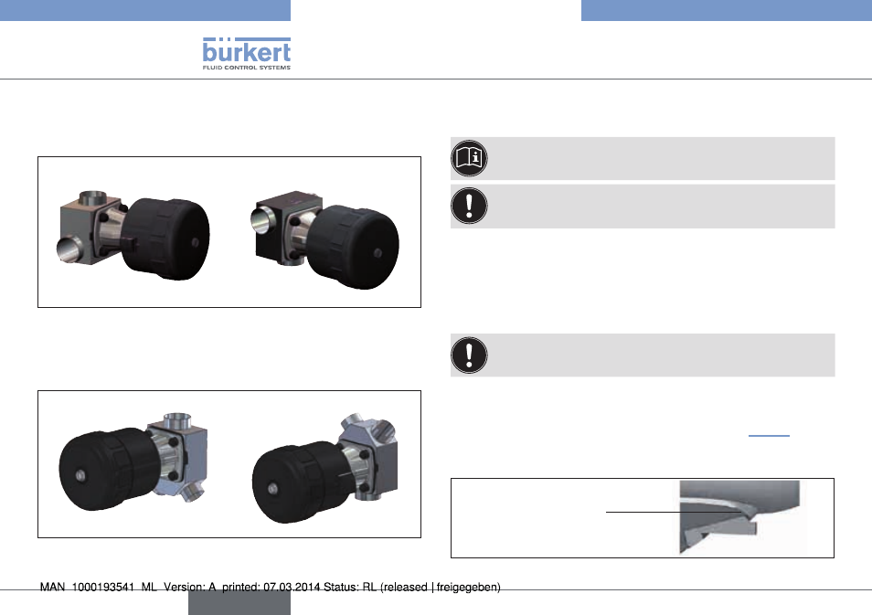
6.2.3 installation position T-valve type 2032
For the installation of the T-valves into circular pipelines, we recommend
the following installation positions:
For supply of a medium:
For removal of a medium:
Fig. 4:
Installation position of type 2032
6.2.4 installation position y-valve type 2037
For the installation of the Y-valves into systems, we recommend the
following installation positions:
For supply of a medium:
For removal of a medium:
Fig. 5:
Installation position of type 2037
6.2.5 installation of tank bottom valve
Type 2033
For information about tanks and welding instructions, refer to
the standard ASME VIII Division I.
We recommend that the valve is welded before the tank is
assembled. However, it is still possible to weld the valves to
completely installed tanks.
before welding, make sure that:
• the tank bottom valve does not impact any other device installation
component and that is always remains possible to assemble and
dismantle the actuator.
• a minimum distance between 2 welding points of 3x the thickness
of the tank wall is maintained.
To ensure that the tank drains optimally, the valve should be
welded in the middle of the drain
The diameter of the holes in the tank and in the flange must be equal.
The valve has two weld edges to simplify welding and positioning of
the valve. The weld edges are about 3 mm long. If the tank wall is more
than 3 mm thick, the valve must be positioned on the „Fig. 6“.
→
Grind the drain wall down,
→
Weld the valve in.
Position to be ground
on tank
Fig. 6:
Position to be ground on tank
english
Type 2030, 2031, 2031 K, 2032,
2033, 2037