Burkert Type 2012 User Manual
Page 3
→
Insert pressure springs
35
.
→
Place intermediate washer
20
and lightly lubricated O-ring
21
on
spindle.
→
Insert pistons
22
and supporting washer
24
.
→
Wet spindle thread
2
with special adhesive LOCTITE 274 and
screw on nut
25
.
→
Mount position indicator
26
.
→
Insert new O-ring
30
into the groove of the actuator body.
Do not damage sealing edges when replacing the seal!
→
Replace graphite seal
5
.
→
Only for VA body: Lubricate nipple thread
6
with Klüber paste
UH1 96-402.
→
Clamp body
1
.
note!
Damage to the seat contour!
• During installation, take care that there is no damage to the seat
contour.
• Observe tightening torques according to “Tab. 1”.
→
Screw in nipple
6
with actuator in valve body
1
.
→
For actuator size G (100 mm) and H (125 mm): Insert washer
40
.
→
Mount cover
31
and screw tightly with special wrench.
→
Check the valve for function and leaks.
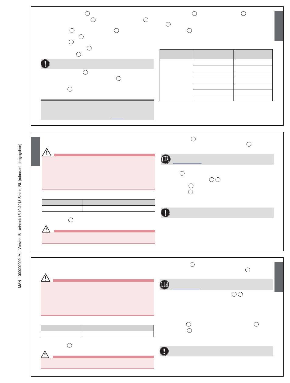
Tightening torques
Material of nipple
thread
DN
Tightening torques
Brass or stainless
steel
15
45
20
50
25
60
32
65
40
65
50
70
65
70
Tab. 1: Valve body tightening torques
English
conveRsIon fRom contRol functIon
a (cfa) to contRol functIon I (cfI)
DAnGer!
Danger – high pressure!
• Turn off the pressure and vent the lines before loosening lines or
valves.
Risk of injury from improper maintenance!
• Maintenance may be performed by authorized technicians only!
• To screw on or unscrew valve body or actuator, use an open-end
wrench, never a pipe wrench, and observe tightening torques.
Required parts:
Item
Description
30
1 O-ring
Procedure:
→
Mount valve
1
on the body.
CAutIon!
Danger through taut springs!
• Carefully open piston actuator!
→
Release cover
31
with special wrench until the springs are
completely relaxed, holding up the actuator body
12
against the
hexagon.
For information about the special wrench, see Chapter
“Installation tools”.
→
For actuator size G (100 mm) and H (125 mm): Remove
washer
40
.
→
Remove pressure springs
28
29
.
→
Insert O-ring
30
into the groove of the actuator body.
→
Mount cover
31
and screw tightly with special wrench.
→
Check the valve for function and leaks.
For control function I (CFI) connect both control air connections
to the control lines.
English
conveRsIon fRom flow above the seat
to flow below the seat
DAnGer!
Danger – high pressure!
• Turn off the pressure and vent the lines before loosening lines or
valves.
Risk of injury from improper maintenance!
• Maintenance may be performed by authorized technicians only!
• To screw on or unscrew valve body or actuator, use an open-end
wrench, never a pipe wrench, and observe tightening torques.
Required parts:
Item
Description
28, 29
1 or 2 Pressure springs
Procedure:
→
Mount valve
1
on the body.
CAutIon!
Danger through taut springs!
• Carefully open piston actuator!
→
Release cover
31
with special wrench until the springs are
completely relaxed, holding up the actuator body
12
against the
hexagon.
For information about the special wrench, see Chapter
“Installation tools”.
→
Remove and / or insert pressure springs
28
29
depending on
actuator.
→
For actuator size C (40 mm), D (50 mm), E (63 mm) and
F (80 mm): Remove pressure springs and insert new, stronger
springs.
→
For actuator size G (100 mm) and H (125 mm): Install new
outer spring
29
in addition to the existing inner spring
28
.
→
Mount cover
31
and screw tightly with special wrench.
→
Check the valve for function and leaks.
Note changed direction of flow and changed pressure range!
English