Burkert Type 2012 User Manual
Page 2
Replacement InstRuctIons
The replacement instructions describe the procedure for converting
the control function of process valves of Type 2000 (angle seat valve)
and Types 2002 and 2012 (globe valves).
These instructions contain important safety information.
Failure to observe these instructions may result in hazardous
situations.
• The instructions must be read and understood before the
conversion.
symbols
→
designates a procedure which you must carry out.
Warning of serious or fatal injuries:
DAnGer!
In case of imminent danger.
WArnInG!
In case of potential danger.
Warning of minor or moderately severe injuries:
CAutIon!
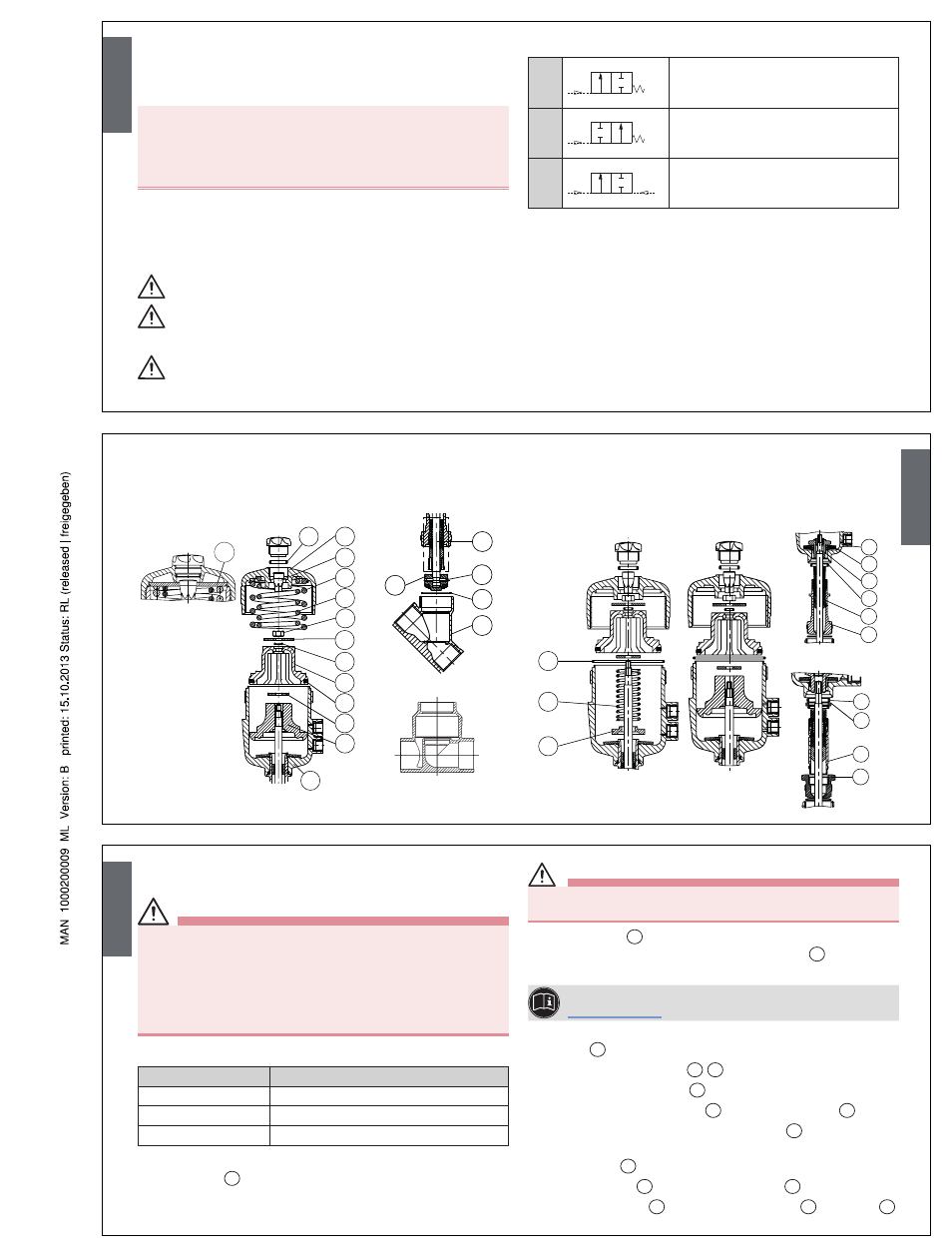
DescRIptIon of the functIons
CFA
P
A
Closed in rest position by spring force
CFB
P
A
Opened in rest position by spring force
CFI
P
A
Actuating function via reciprocal
pressurization
Flow above the seat
The valve is closed by spring force (CFA) with the medium flow.
Medium pressure above the swivel plate supports the closing process
and contributes to sealing the valve seat. The valve is opened by the
control pressure.
Flow below the seat
Depending on the model, the valve is closed against the medium flow
by spring force (CFA) or by control pressure (CFB). Medium pressure
under the swivel plate contributes to opening the valve.
English
Actuators control function B (opened in rest position
by spring force) and I (dual acting)
30
35
19
CFB
CFI
only for version
ANTG E, F
only for version
ANTG D
11
6
10
8
12
17
18
11
7
6
eXploDeD-vIew DRawIng
Actuators control function A (closed in rest position by spring force)
12
19
20
23
22
21
24
25
28
29
26
31
32
CFA
2
4
5
1
3
Body Type
2000 and 2002
Body Type
2012
40
only for version
ANTG G, H
English
conveRsIon fRom contRol functIon
a (cfa) to contRol functIon b (cfb)
DAnGer!
Danger – high pressure!
• Turn off the pressure and vent the lines before loosening lines or
valves.
Risk of injury from improper maintenance!
• Maintenance may be performed by authorized technicians only!
• To screw on or unscrew valve body or actuator, use an open-end
wrench, never a pipe wrench, and observe tightening torques.
Required parts:
Item
Description
35
1 Pressure spring
30
1 O-ring
5
1 Graphite seal
Procedure:
→
Mount valve
1
on the body.
CAutIon!
Danger through taut springs!
• Carefully open piston actuator!
→
Release cover
31
with special wrench until the springs are
completely relaxed, holding up the actuator body
12
against the
hexagon.
For information about the special wrench, see Chapter
“Installation tools”.
→
For actuator size G (100 mm) and H (125 mm): Remove
washer
40
.
→
Remove pressure springs
28
29
.
→
Remove position indicator
26
with Allen key.
→
Screw actuator on the nipple
6
out of the valve body
1
.
→
Carefully screw in actuator on the swivel plate
3
(only put pressure
on the upper section of the swivel plate).
→
Release nuts
25
.
→
Remove pistons
22
with supporting washer
24
.
→
Remove filler piece
19
with intermediate washer
20
and O-ring
21
.
English