Brooks – Brooks Instrument 5851EM User Manual
Page 42
4-4
Brooks
®
Models 5965, 5851EM
Section 4 Maintenance
& Troubleshooting
Installation and Operation Manual
X-TMF-5965-5851EM-MFC-eng
Part Number: 541B122AAG
September, 2009
2. Connect the controller to a source of the gas on which it was originally
calibrated. Command 100% flow and adjust the inlet and outlet
pressures to the calibration conditions. Verify that the output signal
reaches and stabilizes at 5.000 Volts. Vary the command voltage over
the 2-to-100% range and verify that the output signal follows the
setpoint.
Apply +15 Volts to the valve override input (refer to Figs. 2-2, 2-3
and 2-4 for terminal assignments) and verify that the output exceeds
5.000Volts.
Apply -15 Volts to the valve override terminal (connect valve override
pin +0 ground for current l/O versions) and verify that the output signal
falls below 0.100 Volts. lf possible, connect a flow measurement device
in series with the mass flow controller to observe the actual flow
behavior and verify the accuracy of the mass flow controller. lf the mass
flow controller functions as described above, it is functioning properly
and the problem is most likely elsewhere. Table 4-1 lists possible
malfunctions which may be encountered during bench troubleshooting.
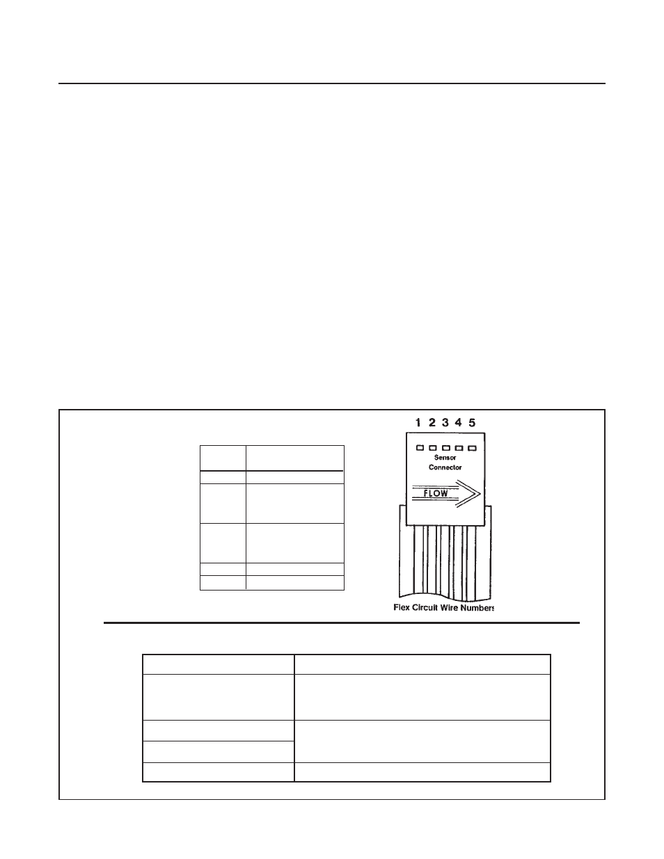
Table 4-2 Sensor Troubleshooting
Remove the sensor connector from the PC Board for this procedure.
OHMMETER CONNECTION
RESULT IF ELECTRICALLY FUNCTIONAL
Open circuit on ohmmeter. If either heater (1) or
Pin 1 or 4 to meter body
sensor common (4) are shorted, an ohmmeter
reading will be obtained.
Pin 4 to Pin 2
Nominal 1100 ohms reading, depending on
Pin 4 to Pin 3
Pin 5 to Pin 1
Nominal 1200 ohm reading.
temperature and ohmmeter current.
SENSOR
SCHEMATIC
PIN
NO.
FUNCTION
1
Heater
Upstream
2
Temperature
Sensor (Su)
Downstream
3
Temperature
Sensor (Sd)
4
Sensor Common
5
Heater Common