Brooks, Table 4-1 bench troubleshooting – Brooks Instrument 5851EM User Manual
Page 41
4-3
Brooks
®
Models 5965, 5851EM
Section 4 Maintenance
& Troubleshooting
Installation and Operation Manual
X-TMF-5965-5851EM-MFC-eng
Part Number: 541B122AAG
September, 2009
B. Bench Troubleshooting
1. Properly connect the mass flow controller to a + 15 Vdc power supply
command voltage source (+27.5 +28 Vdc for Current l/O version) and
connect an output signal readout device (4-112 Digit Voltmeter
recommended) to Terminals 2 and 3 or D-Connector pins 2 and 10
(refer to Figs.2-2,2-3 and 2-9. Apply power, set the command voltage
to zero and allow the controller to warm-up for 45 minutes. Do not
connect to a gas source at this time.
Observe the output signal and, if necessary, perform the zero
adjustment procedure (Section 3-3). lf the output signal will not zero
properly, refer to the sensor troubleshooting section and check the
sensor. lf the sensor is electrically functional, the printed circuit board is
defective and will require replacement.
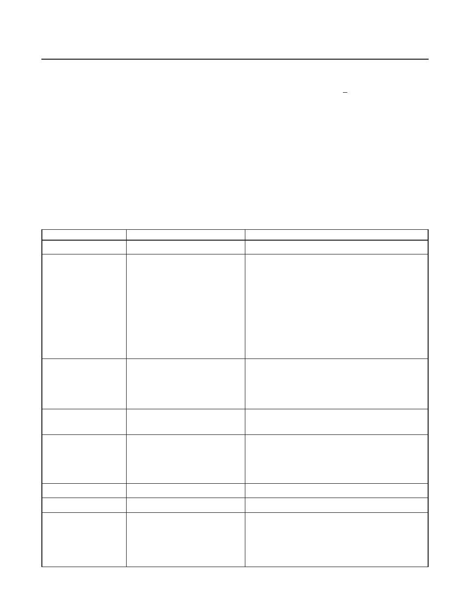
Table 4-1 Bench Troubleshooting
Trouble
Possible Cause
Check/Corrective Action
Actual flow overshoots setpoint by
Anticipate potentiometer out of adjustment.
Adjust anticipate potentiometer. Refer to Section 4 .
more than 5% full scale.
Output stays at zero level regardless
Clogged Sensor tube and restrictor and/or a
Clean sensor. Refer to cleaning procedure, Section 4.
of command and there is no flow
clogged orifice.
through the controller.
Closed or clogged flow path up- or downstream or
Open valve(s). Clean filter(s). Remove any foreign material from gas delivery system.
the controller.
Clogged Control Valve.
Check TP3 with the command at 100%. If the voltage is more negative than -11V,
disassemble and repair the control valve. Refer to Sections 4-3 and 4-4.
Internal reference being used as the command
Refer to Section 3-4, Figure 3-3.
source and the yellow jumper is in the wrong
position.
-15 volts applied to the valve override input
Check valve override input. Refer to Section 2-6 for terminal assignments.
Defective printed circuit board.
Replace printed circuit board. Refer to Section 4-3.
Valve voltage not returned, Pin L at common.
Check jumper for external valve return. Refer to Section 3-4.
"Valve-off" pin grounded.
Check "Valve-Off" input. Refer to Section 2-6 for terminal assignments.
Output signal stays at +6.8 Volts
Valve stuck open or leaky.
Clean and/or adjust control valve. Refer to cleaning procedure and/or Section 4-2D.
(26 mA for Current I/O Vers.) regard-
less of command and there is flow
+15 Volts applied to the valve override input.
Check the valve override terminal. Refer to Section 2-6 for terminal assignments.
through the controller.
Defective printed circuit board.
Replace printed circuit board. Refer to Section 4-3.
Command input floating.
Connect command signal. Refer to Section 2-6 for terminal assignments.
Pin D connected to common.
Remove Pin D from common.
Output signal follows set-point at
Leaky control valve
Disassemble and repair valve. Refer to Section 4-3.
higher commands but will not go to
zero.
Excessive resistance in valve voltage return line.
Reduce wiring resistance or reconfigure controller for "External Valve Return." Refer
to Section 3-4.
Output signal follows set-point at
Insufficient inlet pressure or pressure drop.
Adjust pressures, inspect in-line filters and clear/replace as necessary.
lower commands but does not reach
full scale.
Partially clogged sensor
Check calibration. Refer to Section 3-7.
Partially clogged valve.
Disassemble and repair control valve. Refer to Section 4-3.
Valve out of adjustment.
Adjust valve. Refer to Section 4-4.
Valve guide spring failure.
Check valve spring.
Controller grossly out of calibration.
Partially clogged sensor.
Clean sensor. Refer to the cleaning procedure, Section 4-2D.
Flow is higher than desired.
Controller grossly out of calibration.
Partially clogged restrictor.
Replace restrictor. Refer to Section 4-3.
Flow is lower than desired.
Controller oscillates.
Pressure drop or inlet pressure excessive.
Adjust pressures.
Oversized orifice.
Check orifice size. Refer to Section 4-6.
Valve out of adjustment.
Adjust valve. Refer to Section 4-4.
Anticipate potentiometer out of adjustment.
Adjust anticipate potentiometer. Refer to Section 3-8.
Faulty pressure regulator.
Check regulator output.
Defective printed circuit board.
Replace printed circuit board. Refer to Section 4-3.