Brooks – Brooks Instrument 5851EM User Manual
Page 28
3-2
Brooks
®
Models 5965, 5851EM
Section 3 Operation
Installation and Operation Manual
X-TMF-5965-5851EM-MFC-eng
Part Number: 541B122AAG
September, 2009
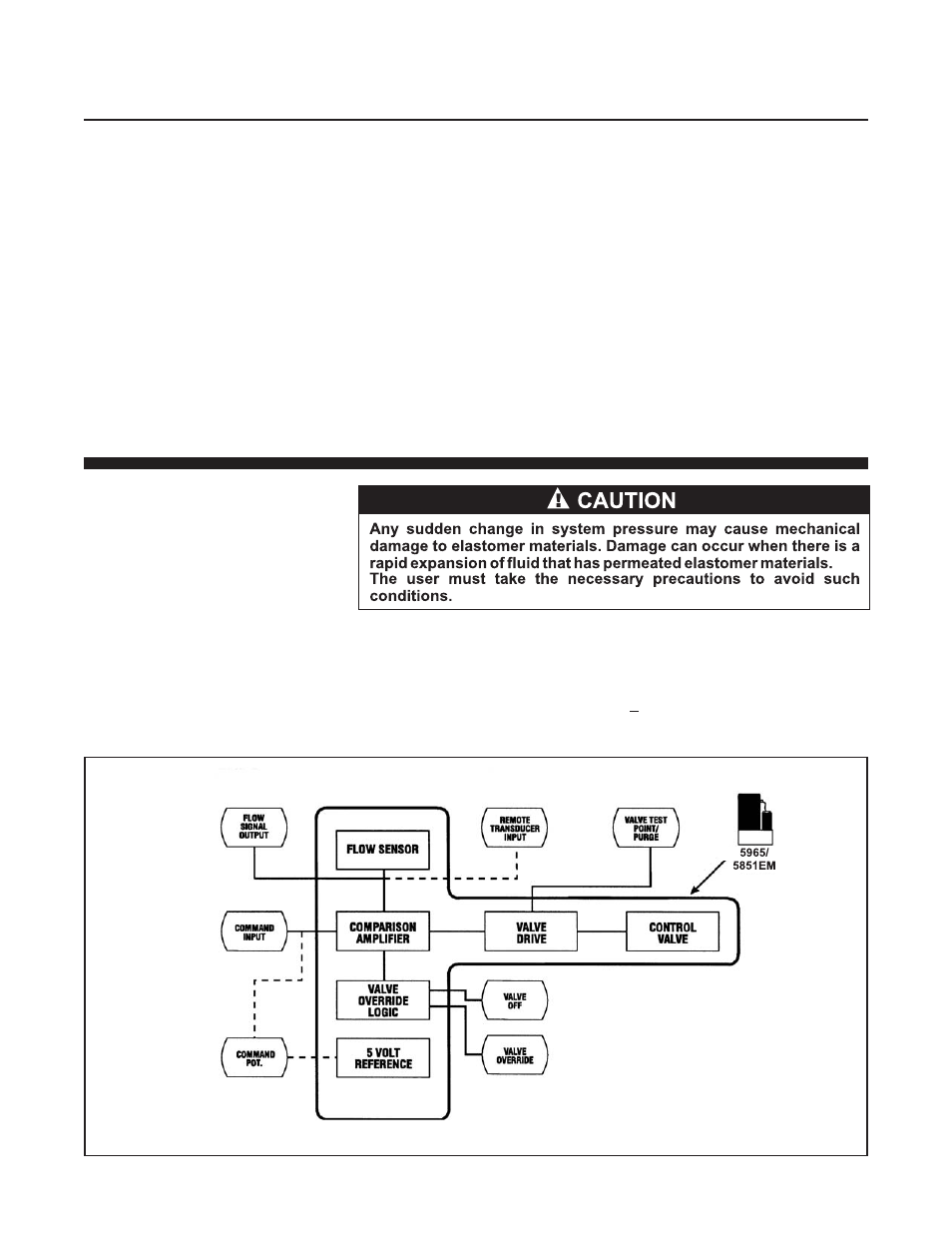
Figure 3-2 Flow Control System Block Diagram
The flow restrictor shown in Figure 3-1 peforms a ranging function similar
to a shunt resistor in an electrical ammeter. The restrictor provides a
pressure drop that is linear with flow rate. The sensor tube has the same
linear pressure drop/flow relationship. The ratio of the restrictor flow to the
sensor tube flow remains constant over the range of the meter. Different
restrictors have different pressure drops and produce controllers with
different full scale flow rates. The span adjustment, in the electronics,
affects the fine adjustment of the controller’s full scale flow
ln addition to the mass flow sensor, the Model 5965/5851EMEM mass flow
controller has an integral control valve and control circuit as shown in
Figure 3-2.The control circuit senses any difference between the flow
sensor signal and adjusts the current in the modulating solenoid valve to
increase or decrease the flow.
3-2 Operating Procedure
a. Apply power to the controller and allow approximately 45 minutes for
the instrument to warm up and stabilize its temperature.
b. Turn on the gas supply.
c. Command zero percent (0%) flow and observe the controller’s output
signal. lf the output is not zero mVdc (+10 mVdc), check for leaks and,
if none are found, refer to the re-zeroing procedure in Section 3-3.