Brooks – Brooks Instrument 5851EM User Manual
Page 34
3-8
Brooks
®
Models 5965, 5851EM
Section 3 Operation
Installation and Operation Manual
X-TMF-5965-5851EM-MFC-eng
Part Number: 541B122AAG
September, 2009
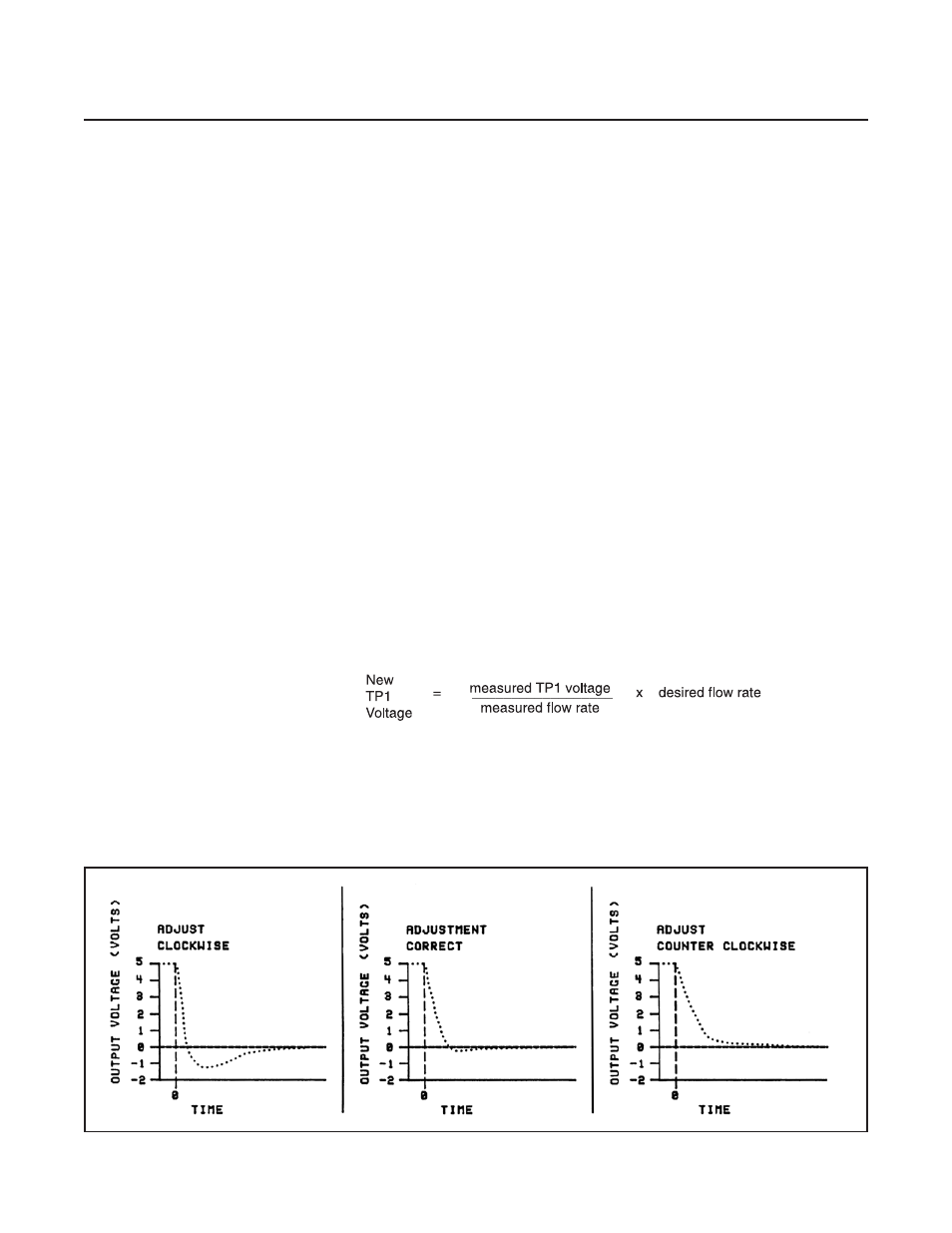
b. Adjust the anticipate potentiometer with 20 clockwise full turns. Next,
adjust the anticipate potentiometer with 10 counterclockwise turns to
center the potentiometer. This will provide a rough adjustment of this
circuit and make the flow more stable for calibration.
c. Connect the DVM positive lead to the 0-5 Volt signal output (Terminal 3
Card Edge, Pin 2 D-Connector) and the negative lead to signal
common (TP4). Adjust the zero potentiometer for an output of zero mv
+2 mV.
d. Apply pressure to the system and insure that the zero signal repeats
within 2 mV of the voltage set in step c above. lf the zero does not
repeat, check for leakage. Note: controllers supplied with all metal or
Teflon valve seats do not provide tight shut-oft. A 0-3% leak-through is
typical. For metal orTeflon seat controllers, close a downstream
shut-off valve and observe the zero signal.
e. Set the command potentiometer (connected to Terminals A, B and 10 of
the Card Edge connector and Terminals 1, 9 and 11 of the
D-Connector) for 100% of flow (5.000 V). Connect the DVM positive
lead to TP2 (linearity voltage) and the negative lead to TP4 (circuit
common). Adjust the linearity potentiometer for an output of 0.0 V
(zero Volts).
f. Connect the DVM positive lead to TP1 (-100x sensor voltage) and the
negative lead toTP4 (circuit common).The command potentiometer
should still be set at 100% flow (5.000 V). Measure the flow rate using
suitable volumetric calibration equipment. To adjust the controller to the
proper full scale flow, calculate a new TP1 voltage using the following
equation:
Figure 3-7 Fast Response Adjustment