Brooks – Brooks Instrument 5851EM User Manual
Page 21
2-7
Brooks
®
Models 5965, 5851EM
Section 2 Installation
Installation and Operation Manual
X-TMF-5965-5851EM-MFC-eng
Part Number: 541B122AAG
September, 2009
1
15
9
8
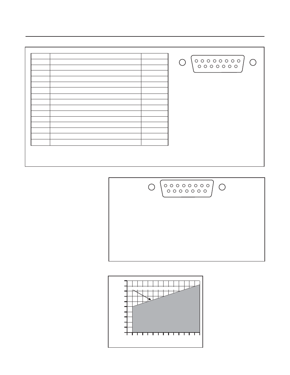
Figure 2-4 Maximum Allowable Loop Resistance
Figure 2-3 D-Connector Pin Arrangement (Current I/O Version)
1. SETPOINT RETURN
2. VOLTAGE SIGNAL OUTPUT
3. NOT USED
4. CURRENT SIGNAL OUTPUT
5. +15 TO +28 Vdc SUPPLY
6. NOT USED
7. CURRENT SETPOINT INPUT
8. VOLTAGE SETPOINT INPUT
9. SUPPLY COMMON
10. SIGNAL OUTPUT RETURN
11. 5V REFERENCE OUTPUT
12. VALVE OVERRIDE INPUT
13. NOT USED
14. CHASSIS GROUND
15. NOT USED
Figure 2-2 D-Connector Pin Arrangement (Voltage I/O Version)
Pin No.
Function
Color Code
1
Command Common (Command Pot "CCW")
Black
2
0-5 Volt Signal Output
White
3
External Valve Return (See Note 3)**
Red
4
Valve Off
Green
5
+15 Vdc Supply
Orange
6
-15 Vdc Supply
Blue
7
Valve Test Point/Purge
Wht/Blk
8
Cmd. Input or Cmd. Pot "S"
Red/Blk
9
Supply Voltage Common
Grn/Blk
10
0-5 Signal Common
Org/Blk
11
+5 Volt Reference Output (Cmd. Pot "CW")
Blu/Blk
12
Valve Override
Blk/Wht
13
Not Used
Red/Wht
14
Chassis Ground
Grn/Wht
15
Remote Transducer Input***
Blu/Wht
1
15
9
8
Note:
1. Cable shield tied to chassis ground in
meter connector. Make no connection
on customer end.
2. All power leads must be connected to
power supply.
3. To use Pin 3 for external valve return,
Jumper J1 must be moved to the B-D
position and Pin 3 must be grounded
at the customer’s system.
4. Pin 9 is normally used for external
valve return and can be used for
cables up to 10 feet in length.
** Jumper Selectable
*** Factory Activated Option
POWER SUPPLY VOLTAGE (VOLTS)
100
200
900
1000
700
800
500
600
300
0
14
27
26
22
21
28
25
400
24
23
20
19
18
17
16
15
T
O
T
A
L LOOP RESIST
ANCE (OHMS)
ALLOWABLE OPERATING RANGE