FlexLink Направляющие и опорные салазки (пластик) Монтаж User Manual
Page 8
466
A. Installation of plastic slide rail and support rail
A. Installation of plastic slide rail and support rail (continued)
Installation of slide rail in XK plain bends
Plain bends increase the tension in the chain and cause
higher stress on the slide rail. It is therefore recom-
mended that slide rail be used on both the upper and
lower flanges in XK horizontal plain bends. Start by
installing the lower slide rail.
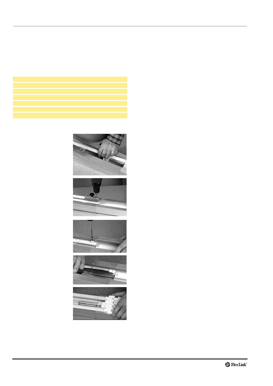
Tools required
Procedure
Installation of slide rail in X180/X300 plain bends
The centre beam in X180/X300 plain bends has an addi-
tional pair of flanges for slide rail inside the beam, similar
to the XK beam type N. Installation is similar to that
described for slide rail in XK plain bends.
Note
For the slide rail inside the beam (inner bend only), plas-
tic screws must be used for anchoring.
Plastic screw XLAG 5 or aluminium rivet XLAH 4×7
can be used for the upper slide rails.
Cutting pliers
Knife
Hammer
Screw driver
Drill 4,2 mm
Drill fixture (Part #3920500)
Plastic screws XWAG 5
1 Mount slide rail on the
lower flange of the con-
veyor beam. Cut the slide
rail at a slight angle, to
ensure a smooth entry of
the chain.
2 Temporarily install a
piece of upper slide rail.
Use the drill fixture to drill
holes in the slide rail on
the upper and lower
flange. Use a drill bit that
is long enough to drill
through both flanges.
3 Anchor the lower slide rail
to the beam using
XWAG 5 plastic screws.
4 Cut off all screw heads.
File off protruding edges.
5 Remove and discard the
temporary piece of upper
slide rail and install the
full length of upper slide
rail. Test the chain track.