FlexLink Направляющие и опорные салазки (пластик) Монтаж User Manual
Page 6
464
A. Installation of plastic slide rail and support rail
A. Installation of plastic slide rail and support rail (continued)
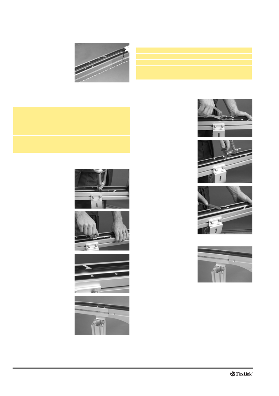
Slide rail in conveyor beam section XLCH 5 V
Anchoring slide rails using aluminium rivets
Tools required
Procedure
Anchoring slide rail using plastic screws
Tools required
Procedure
1 When using articulated
beam section XLCH 5 V,
the slide rail must be
mounted across the
entire beam section, and
cut off at the beginning of
the following beam sec-
tion.
Rivet crimping pliers
XS: Part #3924776,
XL-X85/XM-XH-XK-X180/X300: Part #5051395
or
Rivet crimping clamp
XS: Part #3924770
XL-X85/XM-XH-XK-X180/X300: Part #3923005
Aluminium rivets:
XS: XLAH 3×6
XL-XM-XH: XLAH 4×6
XK-X180/X300: XLAH 4×7 (brown colour)
1 Insert rivets in the holes,
using rivet crimping pliers
or a rivet crimping clamp.
For type of rivet, see
above.
2 If working space is lim-
ited, the rivet crimping
clamp might be easier to
use. The two crimping
tools perform the same
task, but the pliers are
more efficient and easier
to use.
3 Check that the rivets do
not protrude over the sur-
face of the slide rail.
Check both top and
underneath surface of
slide rail for protruding
metal.
4 Keep a distance of
approximately 30 mm
between rivets and idler
unit. This is in case the
idler unit has to be
removed after conveyor
system assembly.
Wrong
Correct
Pliers/screwdriver
Knife
Hammer
Plastic screws:
XS-XL-X85/XM-XH-
X180/X300:
XLAG 5
XK:
XWAG 5
1 Press or screw the
screws into the holes
using a pair of pliers or a
screwdriver.
2 Cut off the screw heads
by using a knife and a
hammer. Cut should be
made away from the joint,
in the direction of chain
travel.
3 Make sure the slide rail
surface is smooth and
that screws do not pro-
trude over the surface of
the slide rail. If the sur-
face should be uneven,
file the edges smooth.
Check both top and
underneath surface of
slide rail for protruding
plastic or metal.
4 Keep a distance of
approximately 30 mm
between screws and idler
unit. This is in case the
idler unit has to be
removed after conveyor
system assembly.