FlexLink Направляющие и опорные салазки (пластик) Монтаж User Manual
Page 7
A. Installation of plastic slide rail and support rail
465
PO
X45
XS
XL
XLP
X85
X85P
XH
XK
XKP
X180
X300
GR
CS
XT
XC
XF
XD
FST
XLX
X85X
X180X
X300X
GRX
CSX
ELV
CTL
TR
APX
IDX
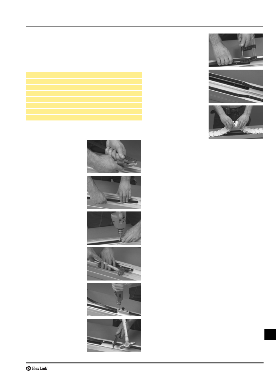
A. Installation of plastic slide rail and support rail (continued)
Slide rail installation – conveyor beam XKCB N
Conveyor beam Type XKCB N has additional flanges for
slide rail “inside” the beam. Attaching slide rail to these
flanges is slightly different from the standard procedure.
This also applies to XK plain bends (see next page).
Tools required
Procedure
Cutting pliers
Hammer
Screwdriver
Clamp
Knife
Drill 4,2 mm
Drill fixture Part #3920500
Plastic screws XWAG 5
1 Cut the slide rail at a 45°
angle.
2 Mount slide rail on the
lower flange of the con-
veyor beam.
3 Drill holes for plastic
XWAG 5 screws.
4 Use a screwdriver to
insert the screws. Cut off
the screw heads using a
knife and a hammer. File
off protruding edges.
5 On the upper flange of
the slide rail, use the drill
fixture to drill two holes in
the slide rail before it
enters the XKCB N beam.
6 Use a screwdriver to
insert the screws. Cut off
the screw heads using a
knife and a hammer. File
off protruding edges.
7 Use a clamp to press the
slide rail on to the beam
flange where the type N
beam begins.
8 Drill one additional hole in
each slide rail at the
beginning of the type N
beam section.
9 Install the chain as shown
in the picture.