Part 2 - electrical installation – Dynasonics 901 Series Enhanced Ultrasonic Flow Meter User Manual
Page 20
Rev.
04/02
-19-
D901/M
If the 0-1mA output has been installed on the D901/M, the
connections are available on the screw terminal block in
the transmitter. Connect a load of not more than 4 K
ohms to the terminals. Adjust control R20 [1 mA] to fine
tune the output to match the load impedance.
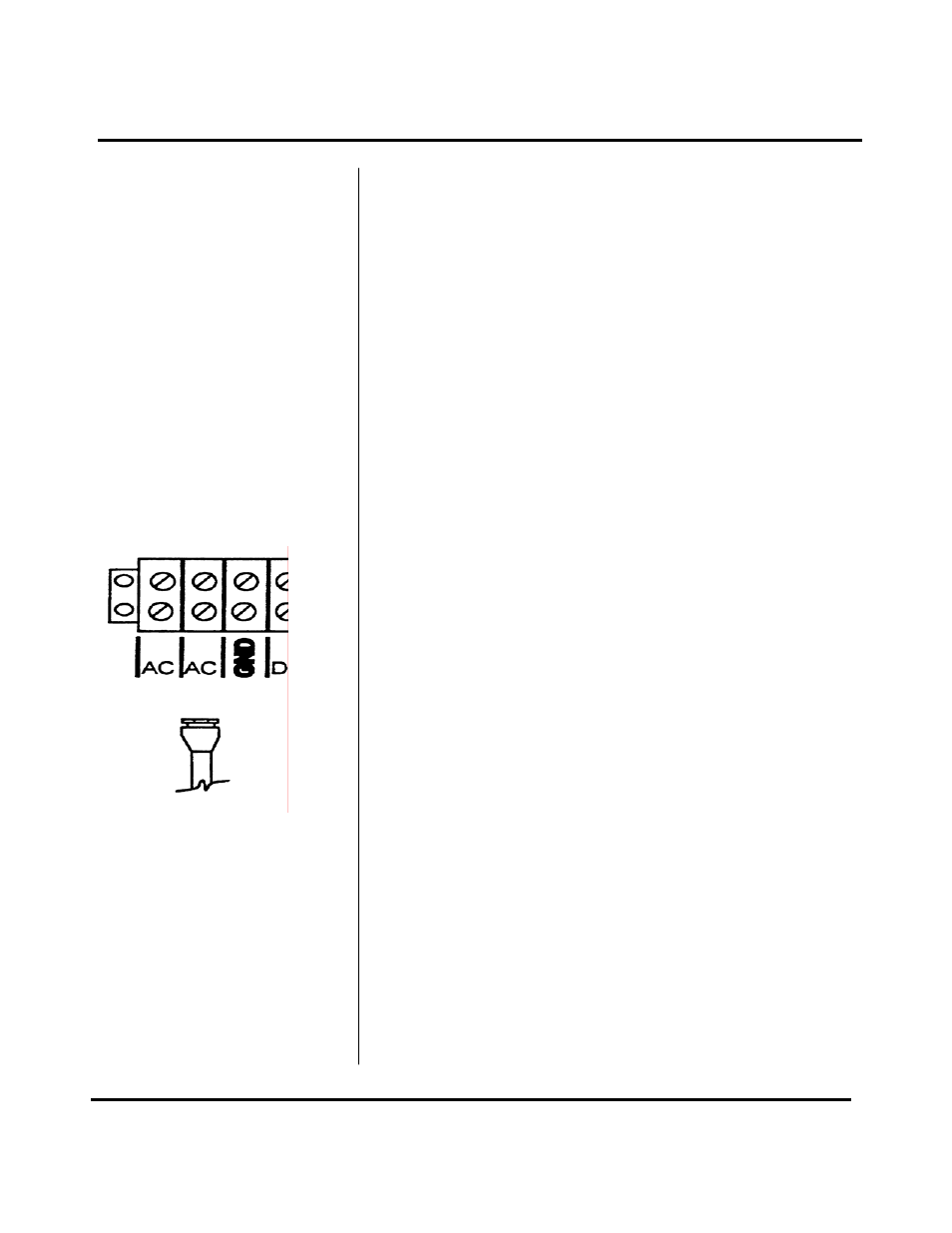
Connect line power to the screw terminals marked AC, AC
and GND in the transmitter. See Figure 10. Utilize the
conduit hole on the left side of the enclosure for this
purpose. Use wiring practices that conform to local codes
(National Electric Code Hand book in the USA). Use only
the standard three wire connection. The ground terminal
grounds the instrument, which is mandatory for safe
operation.
CAUTION: Any other wiring method may be unsafe or
cause improper operation of the instrument.
It is recommended not to run line power with other signal
wires within the same wiring tray or conduit.
NOTE: This instrument requires clean electrical line
power. Do not operate this unit on circuits with noisy
components (i.e. Fluorescent lights, relays, compressors,
variable frequency drives, etc.).
If this option is installed, the D901/M can be operated from
a 12 Vdc source, as long as it is capable of supplying 1
Ampere. Observe proper polarity.
PART 2 - ELECTRICAL INSTALLATION
Optional 12 Vdc power
Figure 10
Line Power
Optional 0 - 1 mA
Output