Part 2 - electrical installation – Dynasonics 901 Series Enhanced Ultrasonic Flow Meter User Manual
Page 19
Rev.
04/02
-18-
D901/M
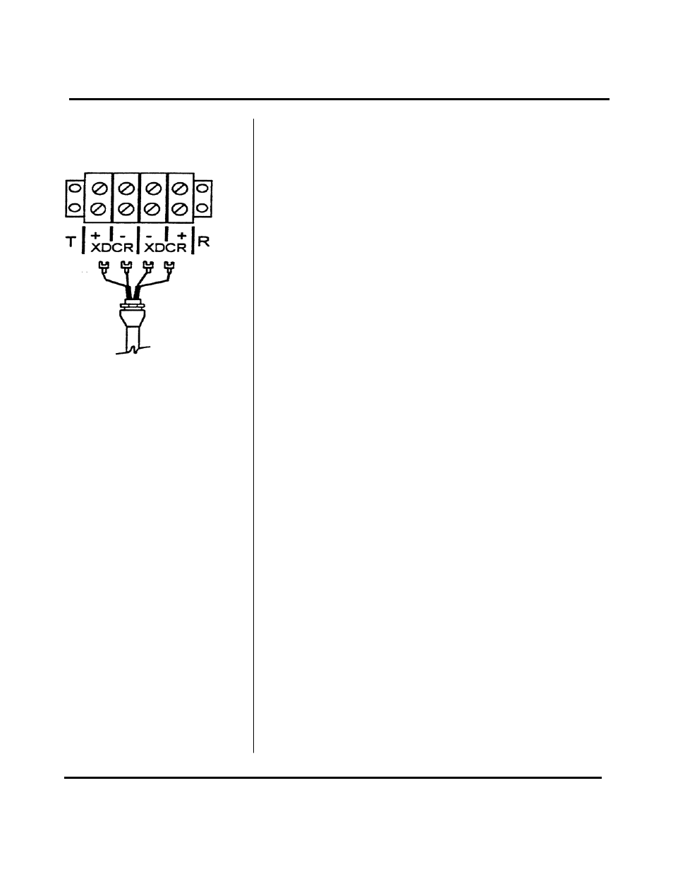
enclosure. Secure the transducer cable with the
supplied conduit nut.
2. The terminals on the transducer cable are coded with
wire markings. Connect the appropriate wires to the
corresponding screw terminals in the transmitter. See
Figure 9.
NOTE: The transducer cable carries low level signals.
Do not attempt to add additional cable to the factory
supplied transducer cable. If additional cable is required,
contact the Dynasonics factory to arrange for an exchange
transducer with the appropriate length of cable. Cables to
300 feet [ 90 meters ] are available.
The 4-20mA output is proportional to the flow rate
measuring scale and can drive a load of up to 600 ohms.
The output is isolated from earth ground and circuit low.
Connect the load to the 4-20 mA screw terminals on the
transmitter terminal block, matching polarity as indicated.
NOTE: An additional hole in the transmitter enclosure is
required for outputs. Drill the hole in the the enclosure
bottom taking care not to drive the drill bit into wiring or the
circuit boards with the transmitter.
The pulse output is proportional to the flow rate measuring
scale. This output may be used one of two ways:
♦ To drive a 12V logic device.
♦ To drive a low impedance, 12V device. Minimum
resistance 50 ohms.
The pulse output is adjustable from a range of 0 - 600 Hz
to 0 - 10kHz via control R29 [CTR] located on the left side
of the signal processing PCB in the back of the enclosure.
The pulse width is fixed at 50 µ seconds. CTR “ - ”
represents circuit low. CTR “ + “ represents 12 Vdc pulse
output.
PART 2 - ELECTRICAL INSTALLATION
Figure 9
Pulse Output
4-20 mA Output
Transducer Connections