Part 2 - transducer installation – Dynasonics 901 Series Enhanced Ultrasonic Flow Meter User Manual
Page 16
Rev.
04/02
-15-
D901/M
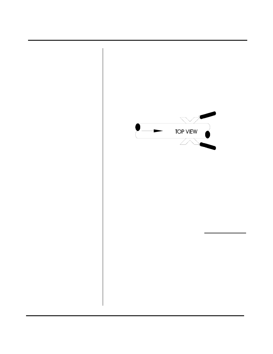
the same direction for proper operation. See Figure 7.
NOTE: Large pipes may require two people for this
procedure.
6. Tighten the strap tight enough to hold the transducers
in place, but not so tight that all of the couplant
squeezes out of the gap between the transducer face
and pipe. Ensure that the transducers are squarely
aligned on the pipe.
7. Route the transducer cable back to the transmitter
mounting area avoiding high voltage cable trays and
conduits. Do not attempt to add additional cable to the
factory supplied transducer cable. The D901/M
processes very small signals, so the cable shield must
be continuous. Excess cable may be coiled to take up
extra length.
8. If the transducers are to be permanently mounted
using Dow 732, the RTV must be completely cured
before proceeding to Instrument Start up. Ensure that
no relative motion between the transducer and pipe
occurs during the 24 hour curing process. If Dow 111
grease was used for temporary operation of the D901/
M system, proceed with the Instrument Start-up
procedures.
Transducer Installation is complete
PART 2 - TRANSDUCER INSTALLATION
Figure 7