Communication Concepts AN779 Application Note User Manual
Page 8
AR
C
HIVE INF
O
RMA
TI
O
N
PRODUCT TRANSFERRED T
O
M/A
–
COM
AN779
8
RF Application Reports
Measurements and Performance Data
The output harmonic contents of this amplifier are
substantially lower than normally seen in a Class AB system
operating at this power level and having a 4.5 octave
bandwidth. All harmonics except the third are attenuated
more than 30 dB across the band. Between 20 and 30 MHz,
– 40 to – 55 dB is typical. The third harmonic has its highest
amplitude (– 20 to – 22 dB), as can be expected, below 20
MHz. The measurements were done at an output level of
20 W CW and with 200 mA collector idle current per device.
Increasing it to 400 mA improves these numbers by 3–4 dB,
and also reduces the amplitudes of d
5
, d
7
, d
9
, and d
11
by
an average of 10 dB, but at the cost of 2–3 dB higher d
3
.
POWER GAIN (dB)
IMD (dB)
58
57
56
55
54
G
PE
d
3
d
5
30
35
40
45
50
V
CC
= 13.6 V, P
out
= 20 W PEP
INPUT
VSWR
2.0
1.5
1.0
45
40
35
(%)
1.5
2
3
5
7
10
15
20
30
f, FREQUENCY (MHz)
η
VSWR
η
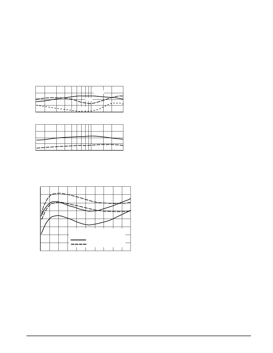
Figure 10. Intermodulation Distortion and Power Gain
versus Frequency (Upper Curves).
Input VSWR and Collector Efficiency (excluding
MHW591) (Lower Curves).
0
-30
-40
-50
-60
-70
4.0
8.0
12
16
20
IMD (dB)
POWER OUTPUT (W PEP)
d
3
d
5
d
3
d
5
V
CC
= 13.6 V
I
cq
= 200 mA PER DEVICE
30 MHz
1.6 MHz
Figure 11. IMD versus Power Output
CONCLUSION
The stability of both designs (excluding the 28 V unit) was
tested into reactive loads using a setup described in
Reference 8. Both were found to be stable into 5:1
load
mismatch up to 7 MHz, 10:1 up to 30 MHz, except the latter
design did not exhibit breakups even at 30:1 in the 20 – 30
MHz range. If the test is performed under two-tone
conditions, where the power output varies from zero to
maximum at the rate of the frequency difference, it is easy
to see at once if instabilities occur at any power level.
The two-tone source employed in all tests consists of a
pair of crystal oscillators, separated by 1 kHz, at each test
frequency. The IMD (d
3
) is typically – 60 dB and the
harmonics – 70 dB when one oscillator is disconnected for
CW measurements.
HP435 power meters were used with Anzac CH-130-4
and CD-920-4 directional couplers and appropriate attenua-
tors. Other instruments included HP141T analyzer system
and Tektronix 7704A oscilloscope-spectrum analyzer
combination.
REFERENCES
1. “Linearized Class B Transistor Amplifiers,” IEEE Journal of
Solid State Circuits, Vol. SC-11, No. 2, April, 1976.
2. Pappenfus, Bruene and Schoenike, “Single Sideband
Principles and Circuits,” McGraw-Hill.
3. Reference Data for Radio Engineers, ITT, Howard & Sams
Co., Inc.
4. H. Granberg, “Broadband Transformers and Power Com-
bining Techniques for RF,” AN-749, Motorola Semiconduc-
tor Products Inc.
5. H. Granberg, “Measuring the Intermodulation Distortion of
Linear Amplifiers,” EB-38, Motorola Semiconductor Prod-
ucts Inc.
6. K. Simons, Technical Handbook for CATV Systems, Third
Edition, Jerrold Electronics Corp.
7. Data Sheets, Motorola MRF475, MRF476, MRF433, and
MHW591
8. H. Granberg, “Two-Stage 1 KW Solid-State Linear Amplifi-
er,” AN-758, Motorola Semiconductor Products Inc.
9. Phillips, “Transistor Engineering,” McGraw-Hill.