Communication Concepts AN779 Application Note User Manual
Page 2
AR
C
HIVE INF
O
RMA
TI
O
N
PRODUCT TRANSFERRED T
O
M/A
–
COM
AN779
2
RF Application Reports
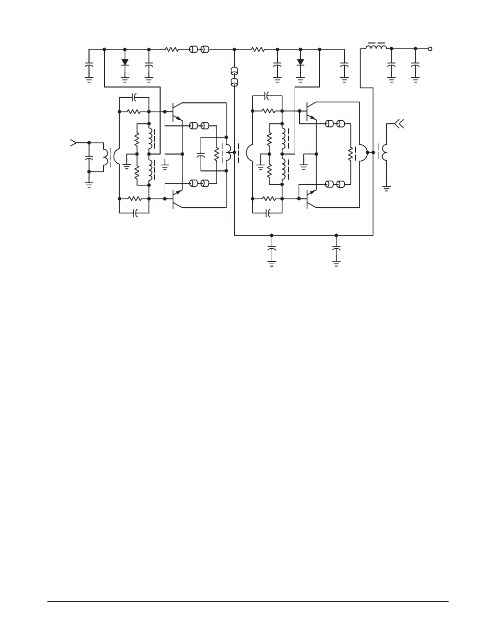
R1, R4 — 10 Ohms, 1/4 W
R2, R3 — 30 Ohms, 1/4 W
R5, R6 — 82 Ohms, 3 W (Nom.)
R7 — 47 Ohms, 1/4 W
R8, R11 — 6.8 Ohms, 1/4 W
R9, R10 — 15 Ohms, 1/4W
R12 — 130 Ohms, 1/4 W
C1 — 39 pF Dipped Mica
C2, C3 — 680 pF Ceramic Disc
C4, C10 — 220
µF, 4 V, Tantalum
C5, C7, C11, C13 — 0.1
µF Ceramic Disc
C6 — 56 pF Dipped Mica
C8, C9 — 1200 pF Ceramic Disc
C12, C14 — 10
µF, 25 V Tantalum
RFC5 — Ferroxcube V K200 19/4B
RFC1, 2, 3, 4 — 10
µH Molded Choke
B — Ferrite Beads (Fair-Rite Prod. Corp. #2643000101 or
Ferroxcube #56 590 65/3B)
D1, D2 — 1N4001
Q1, Q2 — MRF476
Q3, Q4 — MRF475
T1, T2 — 4:1 Impedance Transformer
T3 — 1 :4 Impedance Transformer
C10
V +
C2
+
-
RFC5
D1
+
-
+
-
C4
C1
C13
C14
C12
C11
C9
R11
R10
C7
R12
T3
T2
T1
C5
R6
R5
B
B
B
B
B
D2
RFC4
RFC3
R9
R8
C8
Q3
Q4
Q2
Q1
R2
R3
C3
R4
RFC2
RFC1
C6
R7
50 Ω OUT
50 Ω IN
B
R1
+
-
Figure 2. Schematic and Components Parts List
* NOTE: Parts and kits are available from Communication Concepts Inc., 508 Millstone Drive, Beavercreek, Ohio 45434–5840 (513) 426–8600
This biasing arrangement is only practical in low and
medium power amplifiers, since the minimum current
required through the diode must exceed l
C
/h
fe
.
Gain leveling across the band is achieved with simple RC
networks in series with the bases, in conjunction with
negative feedback. The amplitude of the out-of-phase
voltages at the bases is inversely proportional to the
frequency as a result of the series inductance in the feedback
loop and the increasing input impedance of the transistors
at low frequencies. Conversely, the negative feedback lowers
the effective input impedance presented to the source (not
the input impedance of the device itself) and with proper
voltage slope would equalize it. With this technique, it is
possible to maintain an input VSWR of 1.5:1 or less from
1.6 to 30 MHz.
Impedance Matching and Transformers
Matching of the input and output impedances to 50 ohms,
as well as the interstage matching, is accomplished with
broadband transformers (Figures 3 and 4).
Normally only impedance ratios such as 1:1, 4:1, 9:1, etc.,
are possible with this technique, where the low impedance
winding consists of metal tubes, through which an
appropriate number of turns of wire is threaded to form the
high-impedance winding. To improve the broadband
characteristics, the winding inductance is increased with
magnetic material. An advantage of this design is its
suitability for large-quantity manufacturing, but it is difficult
to find low-loss ferrites with sufficiently high permeabilities
for applications where the physical size must be kept small