Communication Concepts AN779 Application Note User Manual
Page 4
AR
C
HIVE INF
O
RMA
TI
O
N
PRODUCT TRANSFERRED T
O
M/A
–
COM
AN779
4
RF Application Reports
X
X
X
X
X
X
X
X
X
X
X
X
X
X
X
X
X
X
X
X
X
X
X
X
X
X
X
X
X
X
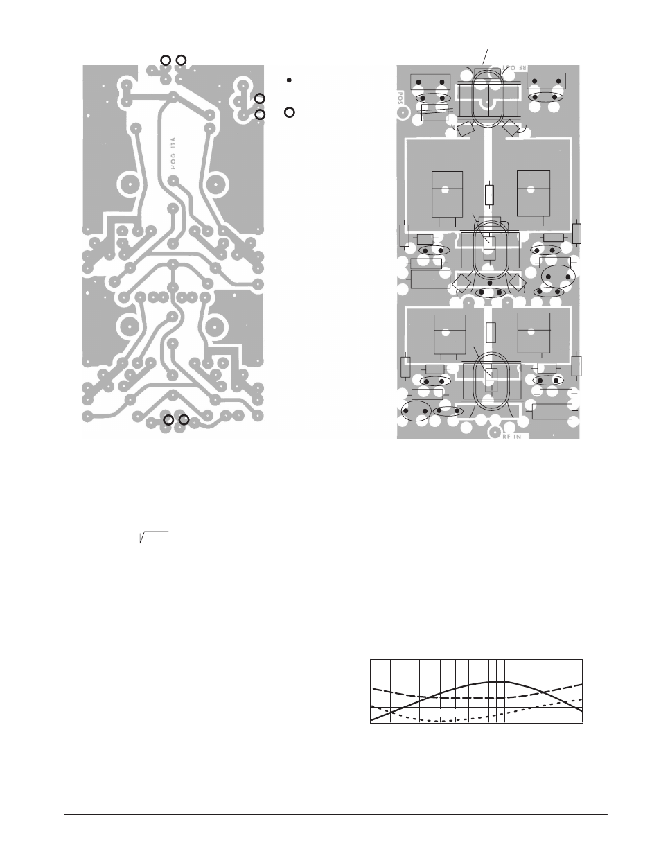
= Feedthrough Eyelets.
= Terminal Pins
R9
Q1
Q2
Q3
Q4
R8
R1
0
R11
C9
C8
R6
C10
C7
C6
RFC4
RFC3
B
B
B
B
C11
C1
2
C1
4
R12
C1
3
RFC5
D2
R7
Beads
Beads
D1
R3
R4
C3
RFC2
R5
C5
C4
RFC1
C2
R1
R2
Figure 5. Component Layout Diagram of Low-Cost 20 W Amplifier
The leads of R7 and R12 form the one-turn feedback windings in T2
and T3. Ferrite beads in dc line can be seen located under T1 and T2.
The input impedance of the MRF476 is 7.55, –j0.65 ohms
at 30 MHz resulting in the base-to-base impedance of
2 x (7.55
2
+ 0.65
2
) = 15.2 ohms.
This, in series with networks R1, C1 and R4, C3 (2 x 4.4
ohms), gives 24 ohms, and would require a 2:1 impedance
ratio transformer for a 50-ohm interface. However, due to the
influence of strong negative feedback in this stage, a better
overall matching is possible with 4:1 ratio. The input net-
works were designed in a manner similar to that described in
Reference 8.
Measurements and Performance Data
At a power output of 20 W CW, all output harmonics were
measured about 30 dB or more below the fundamental,
except for the third harmonic which was only attenuated 17
dB to 18 dB at frequencies below 5 MHz. Typical numbers
for the higher order distortion products (d9 and d11) are in
the order of – 60 dB above 7 MHz and – 50 dB to – 55 dB
at the lower frequencies. These both can be substantially
reduced by increasing the idle currents, but larger heat sinks
would be necessary to accommodate the increased
dissipation.
The efficiency shown in Figures 6 and 7 represents the
overall figure for both stages. Currents through the bias
networks, which are 82/(13.6 – 0.7) = 0.16 A each, are
excluded. Modified values for R5 and R6 may have to be
selected, depending on the forward voltage characteristics
of D1 and D2.
Although this amplifier was designed to serve as a 1.6
to 30 MHz broadband driver, it is suitable for the citizens
band use as well. With some modifications and design
shortcuts, the optimization can be concentrated to one
frequency.
POWER GAIN (dB)
IMD (dB)
30
29
28
27
26
35
40
45
V
CC
= 13.6 V P
out
= 20 W PEP
d
5
d
3
G
PE
Figure 6. Intermodulation Distortion and Power Gain
versus Frequency