Power distribution drawing – ClimaCool SHC onDEMAND 30, 50, 70, 85 Manual User Manual
Page 48
www.climacoolcorp.com
46
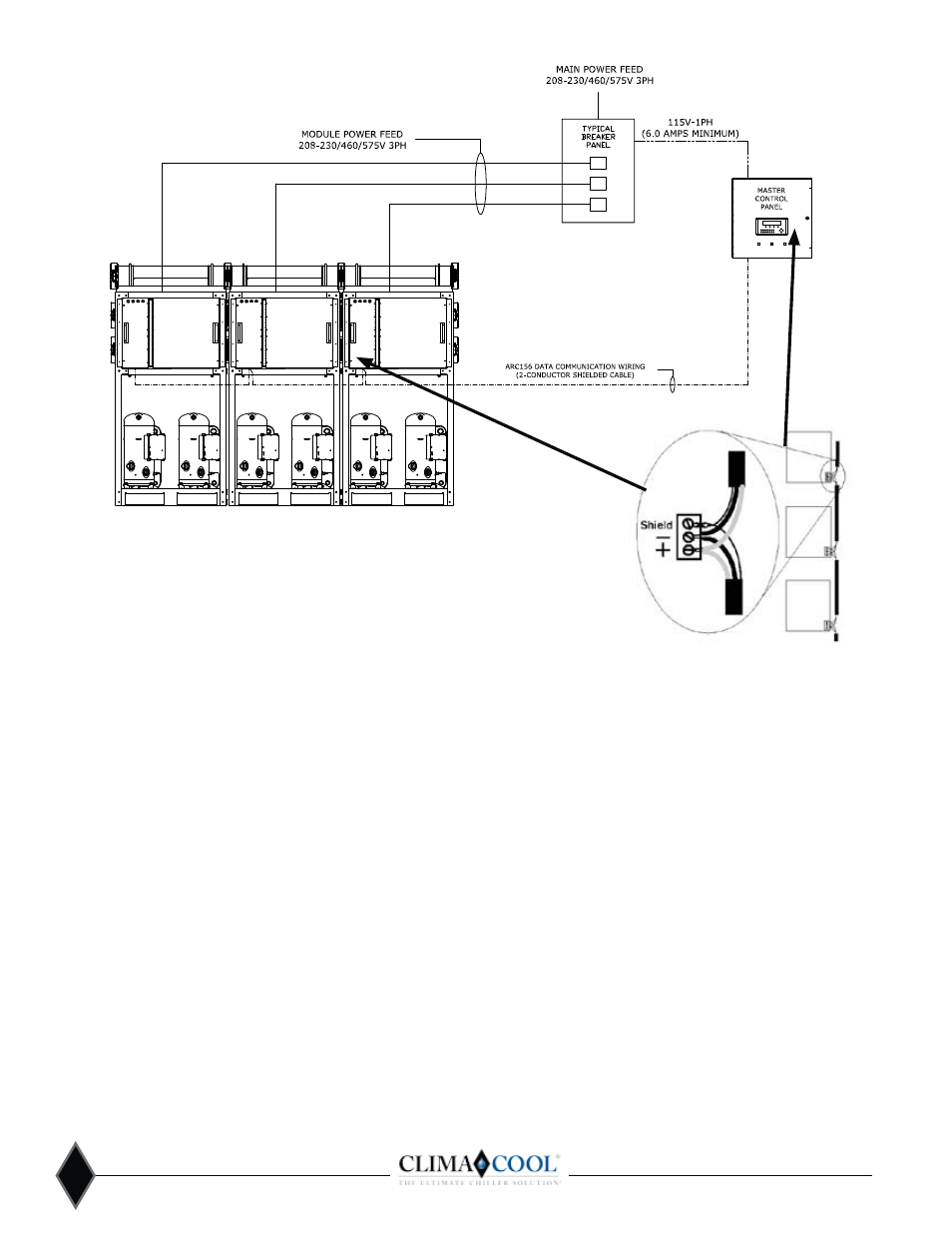
Power Distribution Drawing
Notes:
1.
ƤǤ
Not provided as part of the ClimaCool modular chiller system.
2.
Breaker panels can be supplied for skid mount pump/tank packages or new
construction projects as options. Consult your local ClimaCool Representative.
3.
Control wiring by others.
4. ƤǦ
daisy chain from the master controller to the modules. (See Figure 21).
Figure 21
Ƥ ͕͙͚
• Description - Single twisted pair, low capacitance, CL2P,
TC foam FEP, plenum rated cable
• Conductor - 18 AWG (7x30) stranded copper (tin plated)
0.0.0 in. (0.762mm) O.D.
• Insulation – Foamed FEP, 0.015 in. (0.381mm) wall,
0.060 in. (1.524mm) O.D.
• Twist Lay – 2 in. (50.8mm) lay on pair, 6 twists/foot (20
twists/meter) nominal
• Shielding – Aluminum/Mylar shield with 24 AWG (7x32)
TC drain
• DC Resistance – 15.2 Ohms/1000 feet (50 Ohms/km)
nominal
• Capacitance – 12.5 pF/ft (41 pF/meter) nominal
conductor to conductor
• Characteristic Impedance – 100 Ohms
Cable Shields
Do not ground the shield to earth ground or to the control
module’s power ground. The PROT485 and the individual
ƪ
so that there are no ground loops. If the voltage on the
shield becomes too great relative to the earth ground, then
ơ
PROT485 or on the control modules.
Noise Avoidance
Avoid running communication wires or sensor input wires
next to AC power wires or the control module’s relay output
Ǥ
ơ
quality.
Common sources of noise are:
Spark ignitors
Induction heaters
Radio transmitters
Large contactors (ex.motor starters)
Variable speed drives Video display devices
Electric motors (> 1hp) Lamp dimmers
Generators
Fluorescent lights
Relays
Parallel runs with power lines
Transformers
Other electronic modules
If noise is a problem and you cannot move the wiring,
use ferrite clamp-on chokes on the cabling to improve
signal quality.