Pre-startup, Electrical, Refrigeration – ClimaCool SHC onDEMAND 30, 50, 70, 85 Manual User Manual
Page 25: Warning, Caution
23
www.climacoolcorp.com
Pre-Startup
trained personnel. Prior to chiller startup, there are certain
essential checks which must be completed. Failure to carry
out these checks could result in damage to the chiller
voiding the modules warranty.
Electrical
ơ
and follow proper lock-out/tag-out procedures prior to
servicing any of the chiller’s electrical components. The
Ƥơǣ
1.
The installation must be inspected and approved by the
respective agent and be in compliance with all local and
national electrical codes.
2.
ǤUtilize any lock-out/
tag-out procedures required for your project location
when performing this operation. If no procedure exists,
take all precautions necessary to prevent the power
from being turned on.
Ǥ
ǡ
ǤCheck
connections at each safety and every termination in
the panel.
3. Verify that a separate 115 volt power supply is used to
power the CoolLogic Control System. Field connections
Ƥ
cable daisy chain from the Master Control Panel to the
modules. These control wires must be two-conductor
shielded having #18 AWG minimum up to 50 feet, #16
AWG minimum up to 100 feet, rated at 60°C minimum.
ƤƤȋȌǤ
Power Distribution Drawing on page 46.
4. Ƥ
Ǥ
5. Check all fuses for proper sizing as indicated on the
chiller data plate and/or the electrical diagram on the
inside door of the electrical panel.
6. Verify proper operation of the Ƥ
ơƪǤ
7. ͖͔͜Ȁ͖͔͗ǡ ƤȋȌ
tapped for the measured incoming power supply.
8. Verify proper installation of the
ǡƤȀ.
Refrigeration
1.
Refrigerant piping and components should be inspected
for damage.
2. Place refrigerant gauges on the discharge and suction
access ports of each refrigerant circuit to ensure a
refrigerant charge is present. Leave the gauges on for
compressor rotation check.
3. ƤǤ
1.
Ƥ Ǥ
2. Ƥ
Ǥ
3. Ƥ
in place with both the evaporator and condenser
water systems.
4. Ƥ
water circulating pumps are operational and water is
ƪ
Ǥ
5. Shut the entering water valve and blow out some
water to check for particles or coloration from
Ǥ
ơ
across the chiller and condenser heat exchangers,
measured at the pete’s ports at each module.
6. Ƥ ƪ
condenser and evaporator. Acquire the design
parameters for the chiller bank from the ClimaCool
Selection Program data (available from the local
ȌǤơ
͙
ƪ
ƪǤ
7. Verify proper installation and electrical termination
ǡƤ
installed temperature sensors and wells ȋ
should be fully inserted in the well) and verify
calibration of sensors read through the CoolLogic
Control System.
8. Ƥ Ƥ
condenser and chilled water strainers with a
͚͔
Ǥ
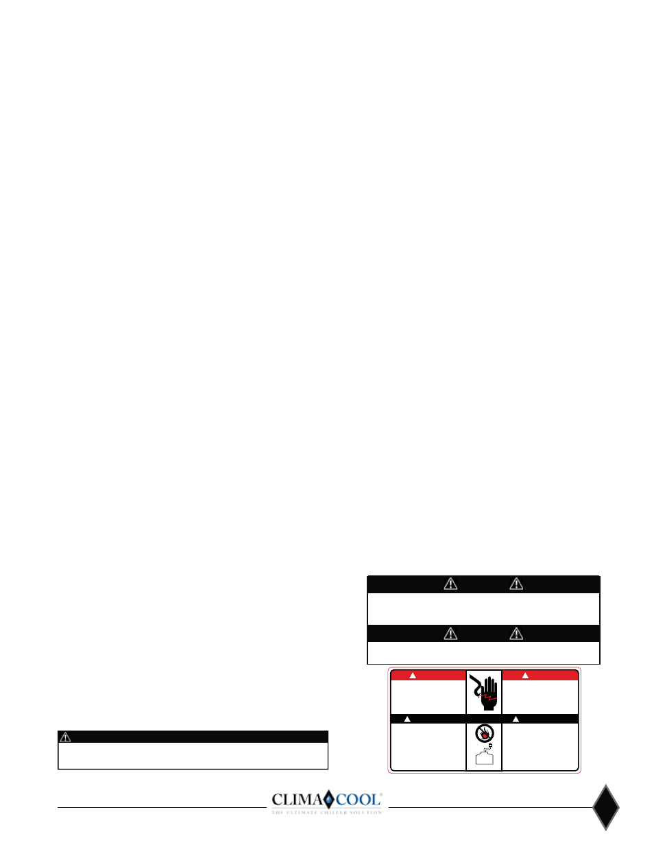
DANGER
(OHFWULFVKRFNKD]DUG
0D\UHVXOWLQLQMXU\RUGHDWK
'LVFRQQHFWSRZHUVXSSO\LHV
EHIRUHVHUYLFLQJ
5HIHUVHUYLFLQJWRTXDOLILHG
VHUYLFHSHUVRQQHO
5LVTXHGHFKRFpOHFWULTXH
5pVXOWDWGHPDLGDQVGRPPDJHV
RXODPRUW
'HEUDQFKHUDYDQWGҋHQWUHSUHQGUH
OHGpSDQQDJHGHOҋDSSDUHLO
&RQVXOWHUXQUpSDUDWHXUTXDOLILH
SRXUOHGpSDQQDJH
DANGER
&$87,21
$77(17,21
8QLWWREHVHUYLFHGE\TXDOLILHG
SHUVRQQHORQO\
5HIULJHUDQWV\VWHPXQGHU
SUHVVXUH
5HOLHYHSUHVVXUHEHIRUHXVLQJ
WRXUFK
5HFRYHUUHIULJHUDQWDQGVWRUHRU
GLVSRVHRISURSHUO\
&RQILHUODPDLQWHQDQFHiXQ
WHFKQLFLHQTXDOLILH
/HV\VWpPHIULJRULILTXHVRXV
SUHVVLRQ
'pFRPSULPHUDYDQWGҋH[SRVHUi
ODIODPPH
5pFXSHUpUOHIULJRULJHQHHWOH
VWRFNHURXOHGpWULUH
FRUUHFWHPHQW
RECOVER
REFRIGERANT
WARNING
This unit contains HFC-(R410A), an azeotropic mixture of R-32 (Difluoromethane) and R-125 (Pentafluoroethane).
DO NOT VENT HFC-(R410A) to the atmosphere. The U.S. Clean Air Act requires the recovery of any residual
refrigerant. Do not use R-22 service equipment or components on R410A systems.
WARNING!
To avoid possible injury or death due to electrical shock, open the
power supply disconnect switch and secure it in an open position
during installation.
CAUTION!
Use only copper conductors for field installed electrical wiring. Unit
terminals are not designed to accept other types of conductors.