Operation instructions, Control switch, Water resistance – ClimaCool SHC onDEMAND 30, 50, 70, 85 Manual User Manual
Page 44
www.climacoolcorp.com
42
Operation Instructions
Flush valve line must be piped to atmospheric pressure such
ƪǤƪ
any changes in elevation and should be sloped downward in
the direction of drainage. ƪ
Ǥǣ
ǦǤ
Ǥǡ
ơơ
ƪƪǡǦ
ǯȋ
Ƥ
ȌǤ
1.
Plug the transformer into a 120-VAC outlet.
2. Insert the 12-VDC plug coming from the transformer into
the jack on the underside of the ATF box.
3. ƪ
control switch (lower switch light should come on the
valve will start to open).
4. Adjust the “ON TIME” (Valve Open) by turning the
inner timer ring with the GREEN POINTER clockwise to
increase duration. The ON TIME RANGE is factory set at
eight seconds. (See Figure 17 on page 41).
5. Adjust the “OFF TIME” (Valve Close) by turning the
outer ring with the RED POINTER clockwise to
increase duration. The OFF TIME RANGE is factory set
at twenty-four hours. (See Figure 17 on page 41).
6. ƪǤơ
on the timer will come on and the upper light on the
Ǥƪ
the on light on the timer and the lower switch light will
come on.
Control Switch
ƪ
down the manual control switch located on the front of
ȋ ͕͕͘͜ȌǤƪ
control switch can also be used to conveniently drain the
water out of the strainer before removing the conical screen
element from the strainer housing. A yellow indicator arrow
on top of the ATF valve will rotate in sync with the ball
valve to show the valve position (open or closed). When
ƪ
ǡ
automatically close.
ǨǦƤ
Ǥ
ƥ
personal injury. Take precaution when handling.
Water Resistance
The Valve and Controller are water-resistant, but not
water-proof. Do not install below ground level where the
component can be submerged in water. Only remove the
cover plate from the Valve Controller when setting or
ƪǤ
on the unit during normal operation.
ơ
ơ
ǯơ
pressure. When the strainer element (conical strainer
Ȍ
Ƥ
ǡ
ơ
Ǧ
ƪǤ
alert maintenance personnel that the strainer element
must be removed and cleaned (See Strainer Element
Cleaning on page 40).
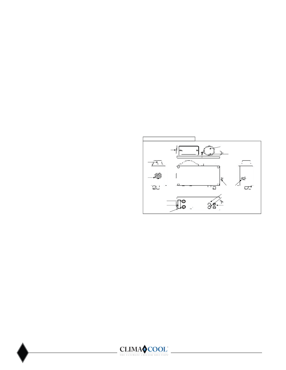
Figure 20
PSID High
PSID Low
Pressure Differential Alarm (PDA) option
Alarm Reset Button
FRONT
VIEW
LEFT SIDE
VIEW
Power To ATF
110 Volt/12 Volt DC
Wall Transformer
Visual
Alarm
Audible
Alarm
Pressure Differential
Switch-Gauge
LED Power Indicator
Differential
Set-Point Contact
Cover-Plate Screw (4) in Corners of
Box (DO NOT REMOVE).
Visual
Alarm
RIGHT SIDE
VIEW
TOP
VIEW
BOTTOM
VIEW
AUX Contacts
(On or Off with Alarm)
Red & Black
Cable Retainer
Operation Instructions
Remove the power supply and insert the connector end into
the socket on the bottom of the PDA housing (See Figure
20 above) and plug the transformer into the power source.
Standard systems are supplied with a 120V power supply to
the primary of the transformer, with an output secondary of
͕͖Ǥơ
Ǧ
͛Ǧ͜Ǥơ
͕ƪ
Ǥơ
͛Ǧ͜ǡƤ
clogged and require immediate removal and cleaning. To
ơ
Ǧǡ
͕Ȁ͕͚dz
ơ
contact to the desired location (See Figure 20). Note: We
ơ
Ǧ
͕͔Ǥ
Ǥ