2 unbalance display pitch, 3 tolerance, 4 printer enabling (optional) – CEMB USA C88 EVO (C) User Manual
Page 24: 5 wheel locking enable, 6 gauge locking enable
24
Use and maintenance manual Rev. 02-2010
ENGLISH
7.8 BALANCING SETUP
7.8.1 Unit of unbalance measurement
It is possible to select whether to display the unbalance values
expressed in grams or ounces.
7.8.2 Unbalance display pitch
This represents the display pitch of the unbalance and varies
according to the unit of measurement selected. The selection
“5 g” (1/4 oz) enables display of the correction values on both
sides such as to bring the static unbalance to 0 (theoretical). It
is recommended to preset this function as standard use of the
machine as it improves the balancing quality. The computer
makes a complex calculation which allows cancelling the
residual static unbalance by varying the value and position of
the counterweights fi xed in steps of 5 grams (1/4 oz).
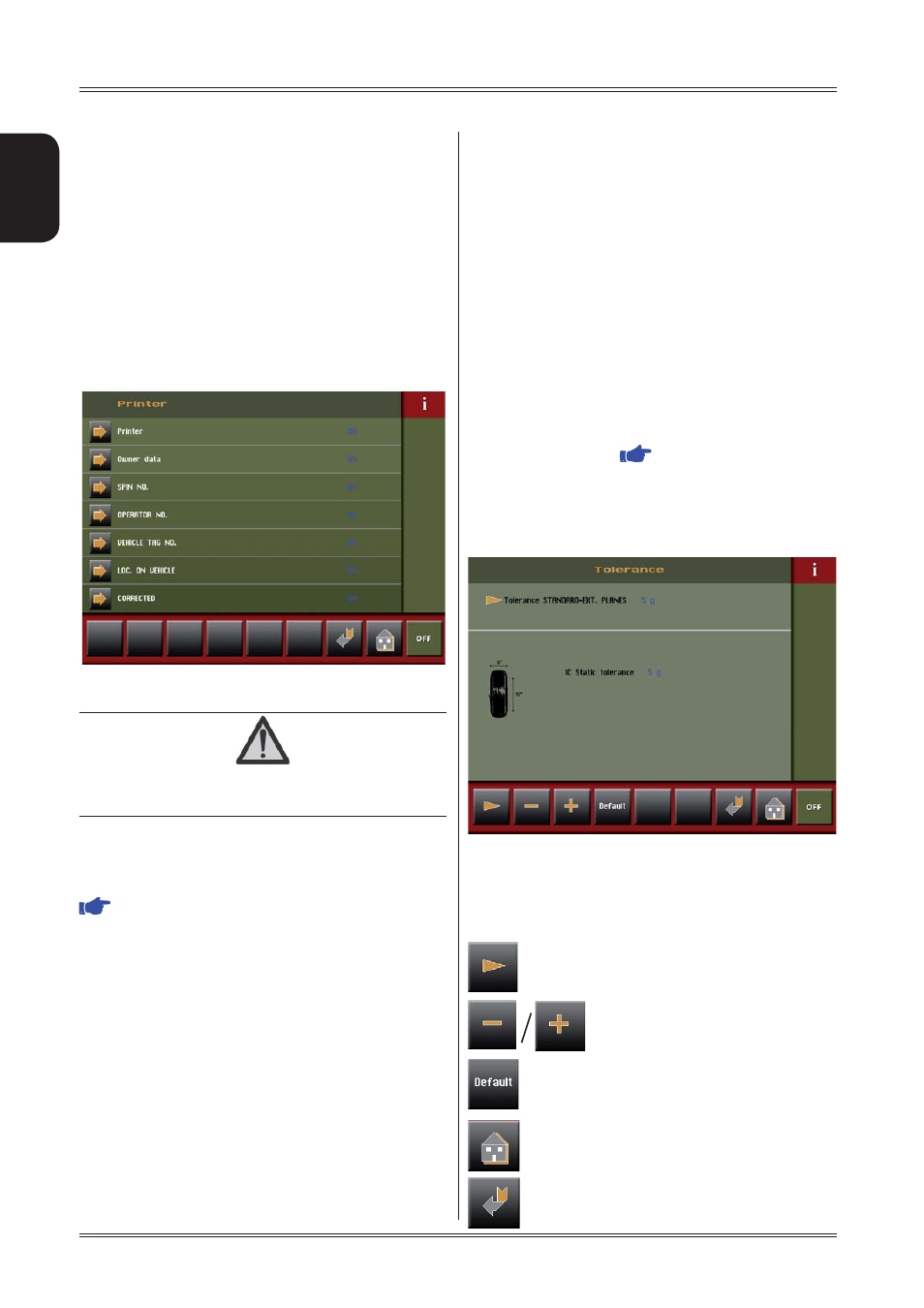
7.8.3
Tolerance (
CORRECTION METHOD
)
This is the unbalance threshold below which the word “OK”
instead of the unbalance value appears on the screen at
the end of the spin:
The tolerance varies based on the correction method selec-
ted. In the case of IC (Intelligent Correction), set the static
tolerance limit and the average weight of a reference wheel
of 6” in width and 15” in diameter.
The following buttons are enabled:
parameter selection during setting
parameter decrease/increase during
setting
default parameter setting recommended
by the manufacturer
return to the measurement screen
return to previous frame.
Setup
Sending sequence is as follows:
- 00000
- Value of correction weight, left side
- Correction phase, left side
- Value of correction weight, right side
- Correction phase, right side
message. The correction values are expressed in grams, in
steps of .1 gram.
The phase values are expressed in degrees, in the range
0 ÷ 359.
7.7.4 Printer enabling (optional)
Enable/disable printer and relative print options.
CAUTION
I
F
THE
OPTIONS
RS232
SERIAL
PORT
AND
PRINTER
ARE
ENABLED
AT
THE
SAME
TIME
,
BOTH
WILL
MALFUNCTION
.
7.7.5 Wheel locking enable
Enables/disables wheel locking in the correction position (
WHEEL LOCKING
).
The possible options are:
OFF: disabled
ON: enabled
ALUS : enables wheel locking in position for the ALUS
correction mode only.
7.7.6 Gauge locking enable
Enables/disables distance gauge locking when the correct
distance has been reached to apply the adhesive weight to
correct the unbalance.
To release the gauge, lower it to below 10” diameter.