2 presetting of tolerance on the machine, 4 value of unbalance corresponding to eccentricity, 11 wheel eccentricity measurements – CEMB USA C88 EVO (C) User Manual
Page 18
18
A
B
Use and maintenance manual Rev. 02-2010
ENGLISH
5.10.2 Presetting of tolerance on the
machine
There is no general rule concerning acceptability of an eccen-
tricity value . As a fi rst approximation we consider it correct
to use a threshold of 1 to 1.5 mm. The E/ECE/324 standard
prescribes 1.5 mm as max. eccentricity of a rebuilt tyre.
5.10.3 Value of static unbalance, correlated
with eccentricity
Clear indication is given in the Measurement screen of both
the value and position of the static unbalance as well as the
eccentricity. In fact, it is interesting to check the correlations
of the two values, above all of the two positions. When the
two positions have a similar angle (± 30° one from the other),
there is a clear sign that an eccentricity is present which
can be compensated by matching.
5.10.4 Value of unbalance corresponding to
eccentricity
For user’s reference, the centrifugal force is calculated corre-
sponding to a certain speed, compared to the force generated
by the eccentricity present on the tyre (calculated with an
approximate average elastic constant).
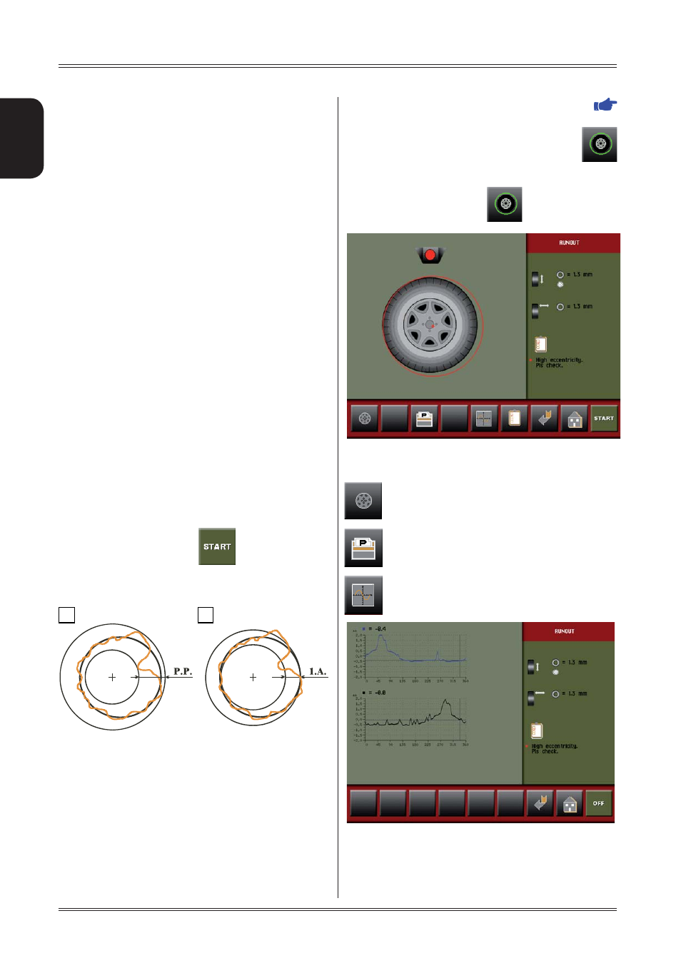
5.11 WHEEL ECCENTRICITY
MEASUREMENTS
The external radial and lateral eccentricity measurements are
automatically made at the end of the unbalance measurement
without having to perform particular procedures.
Remember
to position the sonar sensors in front of the surface to be
measured before pressing the
button.
The much enlarged fi gures show the outer tyre surface and
axis of wheel rotation.
Fig. A
- shows measurement of the total Peak-to-Peak
eccentricity defi ned as maximum radial deviation of the tyre
surface.
Fig. B
- shows measurement of the eccentricity of the 1st
harmonic, i.e. the eccentricity of that circle which “recopies”
the tyre shape, by averaging the local deviations of the tyre
from the round shape.
Obviously the P.P. measurement is normally greater than that
of the 1st harmonic. Tyre manufacturers normally supply two
different tolerances for the two eccentricities.
The maximum limit of the fi rst harmonic can be set (
FIRST HARMONIC LIMIT
). When this limit is exceeded,
the wheel balancer displays the red symbol above the
button to indicate an eccentricity condition that needs to be
corrected. To go to the eccentricity measurement manage-
ment frame, press the button
from the unbalance
measuring frame:
The following buttons are enabled:
to go to rim eccentricity measurement (see the
specifi c chapter)
to print the eccentricity values measured (option)
to display the graph of peak/peak values
Use of the wheel balancer
P/P GRAPH:
represents the peak/peak eccentricity
whose actual value is displayed and
updated by turning the wheel.