4 unbalance measurement (first set of buttons), 1 lock/release wheel in correction position, English – CEMB USA ER100 User Manual
Page 21
21
use and maintenance manual Rev. 11-2011
ENGLISH
Use of the wheel balancing machine
Displays the information screen
Selects unbalance display in g/oz
Displays the threshold
Enables/disables wheel in correction position
Splits the unbalance
Displays the second set of buttons
Lift reset with wheel stopped / STOP during spin
6.4
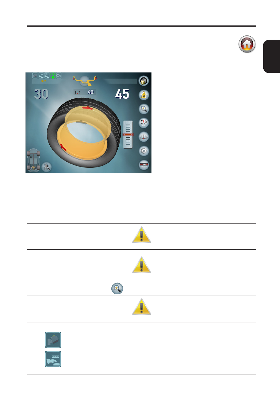
UNBALANCE MEASUREMENT (first set of buttons)
To perform an unbalance measurement spin, close the guard.
After performing a balancing spin, the following are displayed:
The unbalance values.
1.
White: wheel locked in correction position / Internal scanning laser positioned on the side.
▪
Light blue: position not reached / Internal scanning laser not positioned.
▪
The red weights that indicate the unbalance position.
2.
The weight shadows that indicate where the correction weight should be applied: at the top at 12 o’clock or at the
3.
point indicated by the internal laser.
I
f
The
“
Wheel
IN
posITIoN
”
souNd
Is
eNAbled
,
A
souNd
WIll
be
emITTed
WheN
The
coRRecTIoN
posITIoN
hAs
beeN
ReAched
.
I
f
The
uNbAlANce
Is
less
ThAN
The
ThReshold
vAlue
seT
, oK
Is
dIsplAyed
INsTeAd
of
The
uNbAlANce
vAlue
To
INdIcATe
ThAT
The
Wheel
Is
WIThIN
ToleRANce
oN
ThAT
sIde
.
p
RessING
The
buTToN
you
cAN
IN
ANy
cAse
vIeW
The
ResIduAl
uNbAlANce
.
T
o
Resume
WITh
The
dImeNsIoNs
of
The
Wheel
mouNTed
,
opeN
ANd
close
The
spINdle
.
when on, it indicates that the lasers are moving
when on, it indicates that the lift pedal is pressed