Caution – C.E. Niehoff & Co. N1387-1/EPM Troubleshooting Guides User Manual
Page 9
Page 9
TG0019A
(CONT’D)
Section 5: Advanced Troubleshooting
Yes
No
Alternator is defective.
Unplug alternator-to-regulator 4-socket harness from regulator. Connect red lead from DMM to pin A in
plug. Connect black lead to pin D in plug. Does resistance read 2.0 ± 0.2 ohms?
Chart 4
– 28 V LED Flashing AMBER/ 14V LED Off – No Alternator Output – Test OVCO Circuit
Yes
No
Replace existing regulator with known good regulator.
Run engine. Does OVCO trip?
Alternator is defective.
Original regulator
is defective.
T
T
T
T
T
T
T
T
T
T
Chart 3
– 14 V LED Flashing AMBER/ 28V LED Off – No Alternator Output – Test OVCO Circuit
Yes
No
With red lead from DMM connected to pin A in plug, connect black lead to B– terminal. Does
resistance read OL (out of limits)?
Alternator is defective.
T
T
T
T
T
T
T
T
T
T
T
T
T
T
T
T
T
T
T
T
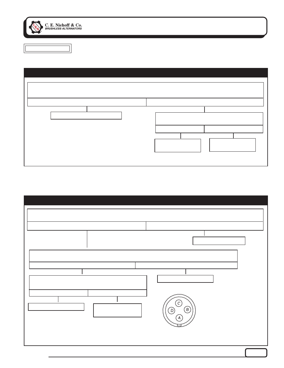
Figure 8 – Alternator-to-Regulator 4-Socket Harness Plug
SOCKET
CONNECTIONS
A
F–
B
Phase Signal AC
C
B–
D
28 V B+
Yes
No
Original regulator
is defective.
Replace regulator with known good regulator.
Run engine. Does OVCO trip?
Alternator
is defective.
T
T
T
T
T
T
T
T
T
T
Yes
No
Alternator is defective.
Unplug alternator-to-regulator 4-socket harness from regulator. At receptacle on regulator, connect red lead
from DMM to pin C. Connect black lead to B– terminal. Does resistance read OL (out of limits)?
T
T
T
T
T
T
T
T
T
T
CAUTION
Troubleshooting sequences must be performed during 3-minute delay after push-button switch on vehicle is
pressed. If main LED on EPM is not flashing GREEN, press switch to reactivate system. LED on EPM must be
flashing GREEN while performing tests.